Feeding device for rod piece machining

The technology of feeding device and rod is applied in the field of feeding device for rod processing, which can solve the problems of trouble and high labor intensity, and achieve the effect of reducing labor intensity, improving applicability, and good stable support

Pending Publication Date: 2022-05-13
厦门市鑫和翔工贸有限公司
View PDF0 Cites 0 Cited by
  • Summary
  • Abstract
  • Description
  • Claims
  • Application Information

AI Technical Summary

Problems solved by technology

[0003] In view of the above-mentioned related technologies, most of the existing rods with small lengths are placed in the storage box first, and then manually placed one by one on the processing station, which is cumbersome and labor-intensive

Method used


Image

  • Feeding device for rod piece machining
  • Feeding device for rod piece machining
  • Feeding device for rod piece machining

Examples


Embodiment Construction

[0034] The following is combined with the attached Figure 1-3 Further elaboration of this application.

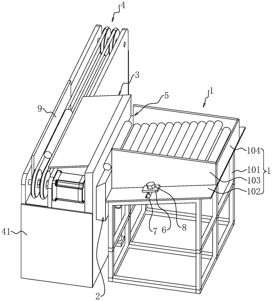
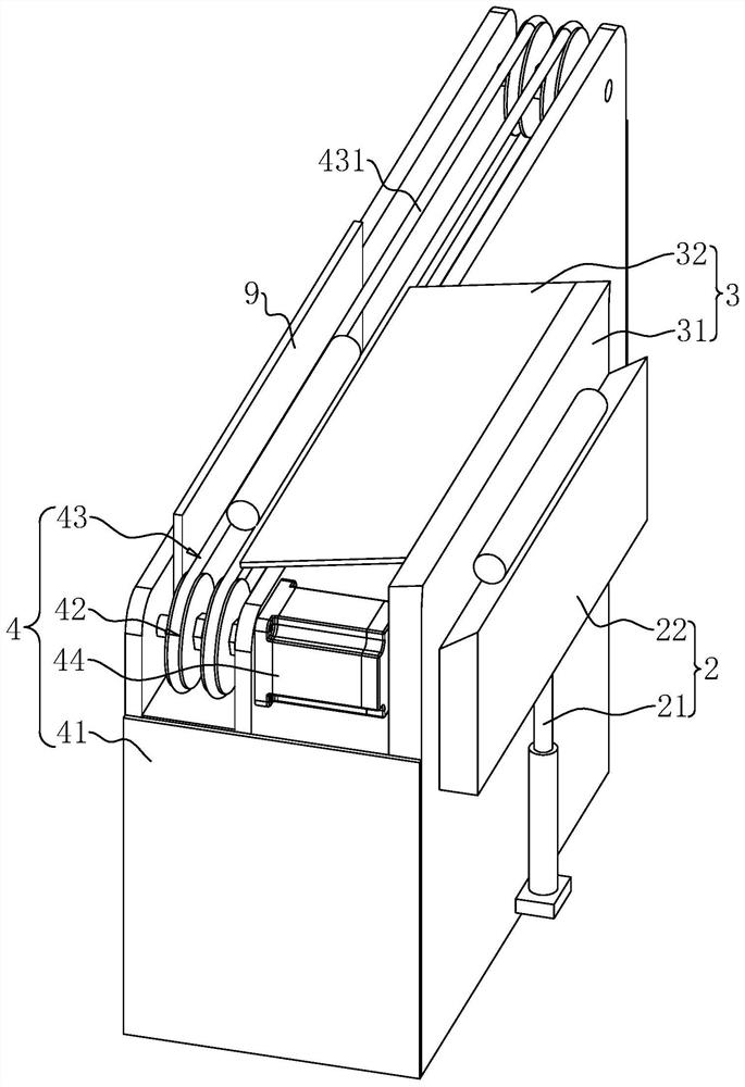
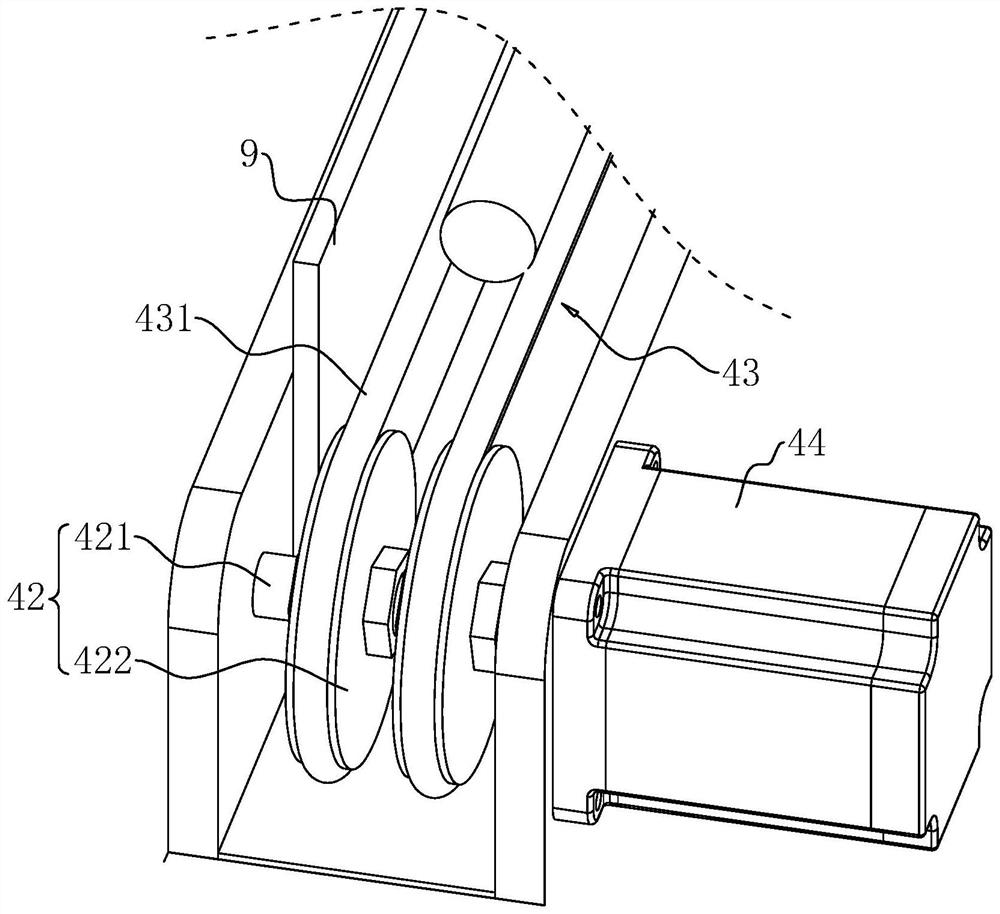
[0035] Embodiment of the present application discloses a member processing feed device, mainly suitable for some cross-sectional circular members for feed transportation. Reference Figure 1 The feeding device comprises a storage box 1, a jacking assembly 2, a guide assembly 3 and a conveying component 4 arranged sequentially in a horizontal direction.

[0036] Storage box 1 for centralized storage of multiple members, storage box 1 on the vertical side is provided with a storage box 1 connected to the bottom of the outlet 5, the bottom of the storage box 1 towards the direction of the outlet 5 downward tilt. Specifically, the storage box 1 includes a support foot 101, a base plate 102 that is obliquely fixed to the upper end of the support foot 101, two parallel and spaced side plates 103 fixed to the upper surface of the base plate 102, fixed to the bottom plate 102 and the t...


PUM


Abstract

The feeding device for rod piece machining comprises a storage box, a discharging opening communicating with the bottom of the storage box is formed in the vertical side of the storage box, and the bottom of the storage box inclines downwards in the direction close to the discharging opening; the jacking assembly is arranged on one side of the storage box, the jacking assembly is located on the outer side of the discharging port, the rod piece close to the discharging port is in lap joint with the upper end of the jacking assembly, and the jacking assembly is used for upwards lifting the rod piece in lap joint with the upper end of the jacking assembly; the guide assembly comprises a blocking part and an inclined part, and when the jacking assembly jacks the rod piece to the upper end of the blocking part, the rod piece freely rolls to the upper surface of the inclined part; and the conveying assembly is arranged on the side, away from the storage box, of the blocking part and located below the inclined part, the rod pieces slide down from the inclined part and then enter the conveying assembly, and the conveying assembly conveys the rod pieces sliding down to the conveying assembly to a machining station. The rod piece conveying device has the effects that the rod pieces can be automatically conveyed conveniently, and the labor intensity is relieved.

Description

Technical field [0001] The present application relates to the field of member processing equipment, in particular to a feed device for member processing. Background [0002] At present, in the production process of accessories, it is often necessary to use some equipment to process pipes, rods, shafts and other member products, especially for the processing of members with small length after cutting, it is necessary to put each member on the processing station, and then process the outer surface through the equipment. [0003] For the related technologies mentioned above, most of the existing members with smaller lengths are first placed in the storage box, and then the members are placed on the processing station by manual means, which is more troublesome and labor-intensive. Contents of the Invention [0004] In order to facilitate the automatic conveying of members and reduce labor intensity, the present application provides an infeed device for member processing. [0005] T...

Claims


Application Information

Patent Timeline
Patent Type & Authority Applications(China)
IPC IPC(8): B65G47/82B65G15/20B65G47/88B65G21/14
CPCB65G47/82B65G15/20B65G47/8838B65G21/14B65G2201/0217B65G2207/08
Inventor 江福星
Owner 厦门市鑫和翔工贸有限公司
Why Eureka
Try Eureka