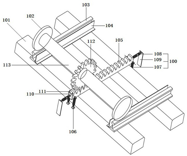
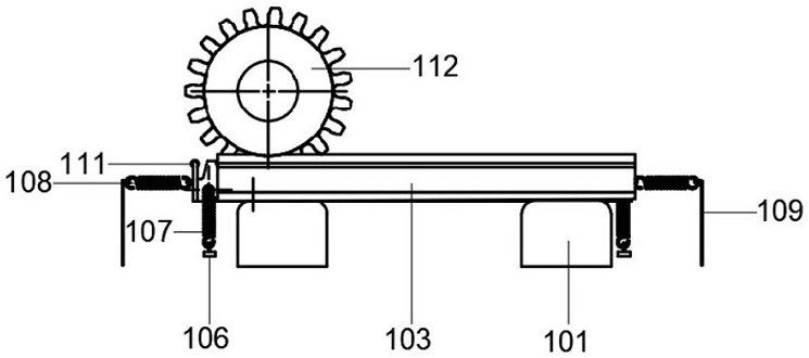
However, the device structure and connection relationship of most rack guide devices are extremely complicated at present, with high design, manufacturing and operation and maintenance costs, and it is difficult to repair and replace once damaged; secondly, when the rack vehicle just enters the rack guide device , prone to
stuttering and
hysteresis, which is not conducive to the continuous meshing between the gear and the rack
[0005] In addition, the problems of the prior art also include that the installation position and direction of the elastic
potential energy parts are single, and the corresponding anti-movement effect is very limited, and the anti-movement mostly depends on rigid components with fixed positions (such as support arms, limit baffles, etc.) ), when the cog rail in the transition section alternately or simultaneously produces movement in various directions under the action of the rack
train (for example, the first movement along the length direction of the rack, the second movement along the width direction of the rack, and the movement along the When the third movement in the height direction), due to the restriction of the rigid anti-movement components on both sides of the transition section rack, coupled with the structure and orientation restrictions of each compression spring, the deformation of each compression spring at least in the front, rear and left and right directions is Extremely limited, because the rigid components often do not have the ability to restore themselves, when the transition section rack is used for too long and the structure is old or subjected to severe
impact, the rigid anti-movement components on both sides of the transition section rack will produce irreversible damage. When damaged and deformed, the rigid anti-movement component is likely to be detached from the original fixed point or the original anti-movement effect is greatly weakened, which will lead to significant effectiveness in restricting the forward and backward, left and right movement of the transition section rack At this time, it is difficult to maintain the original position of the transition section rack only by relying on a single compression spring on the side of the transition section rack, and cannot effectively limit its movement, and due to the structural characteristics of the rigid anti-movement component, it also limits The free deformation range of the corresponding compression spring makes it unable to make up for its lack of strength in preventing the transition section rack from moving when the rigid anti-moving component is damaged
[0006] Secondly, most of the existing rack guide devices basically rely on the rigid anti-movement components on both sides of the transition section rack to limit the movement of the transition section rack, especially at the moment of contact between the rack
train gear and the transition section rack Rigid anti-movement components often have a relatively blunt and strong
impact on the transition section rack. In addition, if the speed of the train is fast, the
impact will be more obvious, so that passengers inside the train will have a strong sense of impact and vibration
In particular, shocks and shocks are not only likely to cause physical and mental discomfort to passengers, but especially when the starting section of the cog train has a certain slope, the effect of the shocks and shocks may be further amplified, which may cause unexpected personal risks
Furthermore, as the rack train continues to move along the length direction of the transition section rack, the strain
potential energy accumulated by the anti-movement member continues to accumulate and reaches a peak at least when the gear of the rack train moves to the transition section rack exit end, However, when the rack train drives out, unlike the compression spring, the release of its internal strain
potential energy is instantaneous and does not have an obvious slow-release effect. At this time, it will produce a phenomenon similar to jerking the transition section of the rack, causing the rack train to In the stage of leaving the transition rack and entering the rack guide, the corresponding pulling feeling may be generated again, hindering the transition of the rack train from the slave rail section to the rack rail section, and as the rack train continues to move, once the rigid anti- The movement member produces a certain degree of deformation damage, which will continue to expand with the continuous movement of the cog train, and is often irreversible, and its corresponding anti-movement ability will continue to weaken or even disappear. The rest of the spring return parts can not fully play their limiting role
[0007] In addition, the rigid anti-tampering components are usually custom-made based on an all-round simulated
force analysis of the transition section of the cog rail during the entry of the rack train, and are basically designed and manufactured in conjunction with the transition section of the cog rail. Damage to the moving components involves the maintenance and replacement of a large number of small and precise parts, which will undoubtedly increase the cost of
manufacturing operations, and only for a single small part, it may take tens of minutes to replace it. It involves the need to make corresponding adjustments to the positional relationship between the cog rail and the rigid anti-movement components in the transition section. For the
daily operation and maintenance of the cog train, especially for the line change or transfer of the cog train, once the fine parts are involved Replacement will increase the
waiting time and bring a lot of inconvenience to passengers


