
Auxiliary feeding and discharging device for oil exploitation casing pipe

A technology for oil exploitation and casing, which is applied in the direction of casing, drill pipe, earthwork drilling, etc. It can solve the problems of large volume, manual handling hazards, and more manpower consumption, so as to avoid card damage, improve handling efficiency, Avoid the effect of shifting

Pending Publication Date: 2022-05-13
涂志发
View PDF0 Cites 0 Cited by
  • Summary
  • Abstract
  • Description
  • Claims
  • Application Information

AI Technical Summary

Problems solved by technology

[0004] In order to overcome the shortcomings of people transporting the casing to the drilling area, because the casing is heavy, the drilling depth is deep, manual handling is more dangerous, and it requires more manpower and larger volume, the technical problem of the present invention is : To provide a casing auxiliary loading and unloading device for oil production that can reduce manual operations, has high handling efficiency, is small in size, simple in operation, and occupies a small area

Method used


Image

  • Auxiliary feeding and discharging device for oil exploitation casing pipe
  • Auxiliary feeding and discharging device for oil exploitation casing pipe
  • Auxiliary feeding and discharging device for oil exploitation casing pipe

Examples


Embodiment 1

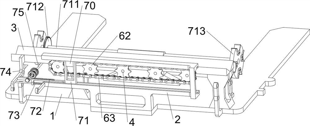
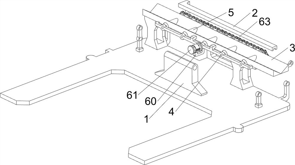
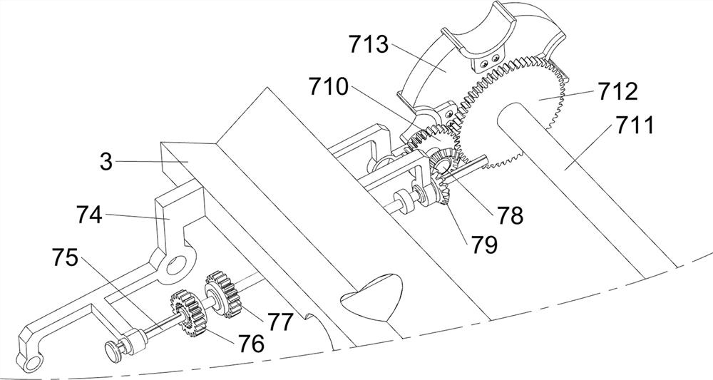
[0082] An oil production casing auxiliary loading and unloading device, such as figure 1 , figure 2 , image 3 , Figure 4 , Figure 5 , Figure 6 , Figure 7 and Figure 8 As shown, it includes a base 1, a slide rail frame 2, a support seat 3, a first rotating shaft 4, a roller 5, a power mechanism 6, a feeding mechanism 7 and a feeding mechanism 8, and the right side of the top of the base 1 is provided with a slide rail frame 2 , the right side of the base 1 top is provided with a support seat 3, the support seat 3 is located at the left side of the slide rail frame 2, and the top of the support seat 3 is rotatably provided with five first rotating shafts 4, and five first rotating shafts 4 are all provided with There are rollers 5, and the rollers 5 are rotated and matched with the support base 3. A power mechanism 6 is arranged between the five first rotating shafts 4. A feeding mechanism 7 is arranged in the middle of the top of the base 1. The feeding mechanism 7...

Embodiment 2

[0091] On the basis of Example 1, such as figure 1 , figure 2 , Figure 9 , Figure 10 and Figure 11 As shown, a switching mechanism 9 is also included, and the switching mechanism 9 includes a support rod 90, a reel 91, an electric push rod 92, a push rod 93, a fixed rod 94, a pull cord 95, a first limit rod 96 and a return spring 97, a support rod 90 is provided between the slide rail frame 2 and the right side of the second support frame 74, and a reel 91 is rotated on the support rod 90, and an electric push rod 92 is installed on the front side of the top of the base 1, and the electric push rod 92 telescopic rods are provided with a push rod 93, the rear side of the push rod 93 is provided with a fixed rod 94, a stay cord 95 is connected between the second rotating shaft 75 and the fix rod 94, and the stay cord 95 is wound on the reel 91, The front bottom of the support seat 3 is provided with a first stop rod 96, the first stop rod 96 is slidably matched with the ...


PUM


Abstract

The invention relates to an auxiliary feeding and discharging device, in particular to an auxiliary feeding and discharging device for an oil exploitation casing. The auxiliary feeding and discharging device for the oil exploitation casing can reduce manual operation, and is high in carrying efficiency, small in size, easy to operate and small in occupied area. An auxiliary feeding and discharging device for an oil exploitation casing pipe comprises a base, a sliding rail frame, a feeding device and a discharging device, the supporting seat is arranged on the other side of the top of the base and located on the left side of the sliding rail frame; and five first rotating shafts are rotationally arranged at the upper part of each supporting seat. The sleeve feeding and discharging device has the beneficial effects that a limiting plate limits a sleeve, the sleeve is prevented from deviating in the feeding and discharging process, a second return spring plays a buffering role, and the situation that the sleeve is clamped and damaged due to deviation is avoided.

Description

technical field [0001] The invention relates to an auxiliary loading and unloading device, in particular to an auxiliary loading and unloading device for oil production casing. Background technique [0002] Oil casing is a steel pipe used to support the walls of oil and gas wells. Each well uses several layers of casing according to different drilling depths and geological conditions. Therefore, people need to carry the casing to the drilling area. The casing is heavy, the drilling depth is deep, and manual handling is dangerous and requires a lot of manpower. At the same time, manual handling has caused a burden to people to a certain extent, and the handling efficiency is also low. The existing auxiliary casing loading and unloading The volume of the installation equipment is relatively large, the operation is relatively complicated, and the occupied area is relatively large. [0003] Therefore, there is a need for an auxiliary casing loading and unloading device for oil ...

Claims


Application Information

Patent Timeline
Patent Type & Authority Applications(China)
IPC IPC(8): E21B19/14
CPCE21B19/14
Inventor 涂志发
Owner 涂志发
Learn More