
Oil pipe joint forming machine

A technology for oil pipe joints and molding machines, which is applied in the direction of assembly machines, metal processing equipment, manufacturing tools, etc., and can solve problems such as increased cost of mechanical structures, difficult mechanical equipment, and large errors

Active Publication Date: 2021-07-06
温州嘉信机械制造有限公司
View PDF7 Cites 0 Cited by
  • Summary
  • Abstract
  • Description
  • Claims
  • Application Information

AI Technical Summary

Problems solved by technology

[0003] Since the current machinery is mass-produced in factories, the efficiency of manual processing is difficult to meet mass production, and errors are prone to be too large in the process of manual processing, resulting in unqualified product processing and wasting a lot of human resources. , reducing work efficiency;
[0004] The material of the pipe is rubber, and the rubber pipe is not straight, so it is difficult to use mechanical equipment to operate the pipe in feeding, discharging and positioning, which increases the cost of mechanical structure and processing cost

Method used


Image

  • Oil pipe joint forming machine
  • Oil pipe joint forming machine
  • Oil pipe joint forming machine

Examples


Embodiment Construction

[0032] In order to make the object, technical solution and advantages of the present invention clearer, the present invention will be further described in detail below in conjunction with the accompanying drawings and embodiments. It should be understood that the specific embodiments described here are only used to explain the present invention, not to limit the present invention.

[0033]In describing the present invention, it should be understood that the terms "longitudinal", "transverse", "upper", "lower", "front", "rear", "left", "right", "vertical", The orientations or positional relationships indicated by "horizontal", "top", "bottom", "inner", "outer", etc. are based on the orientations or positional relationships shown in the drawings, and are only for the convenience of describing the present invention, rather than indicating or It should not be construed as limiting the invention by implying that a referenced device or element must have a particular orientation, be ...


PUM


Abstract

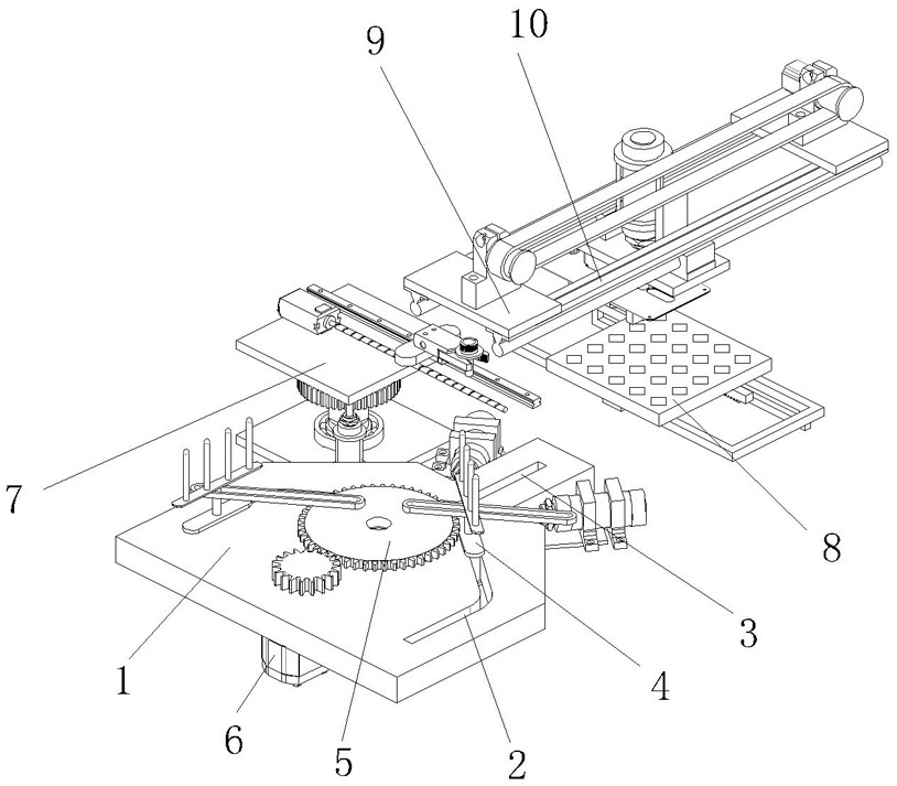
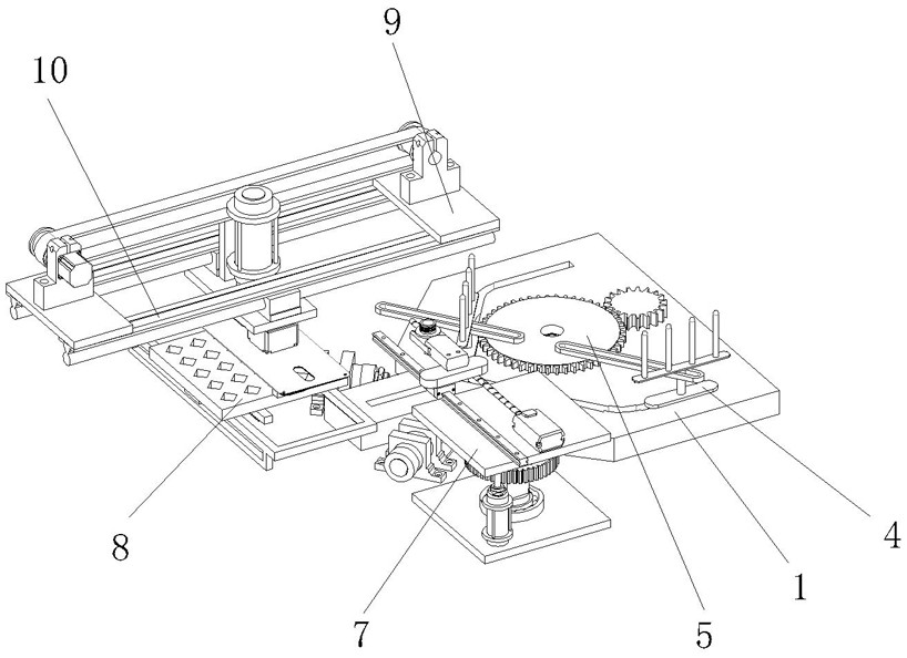
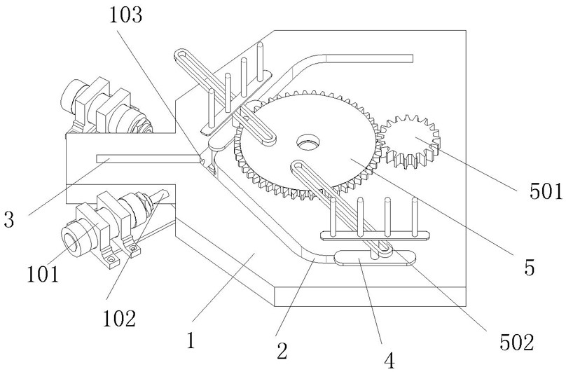
The invention discloses an oil pipe joint forming machine, and belongs to the field of oil pipe machining. The oil pipe joint forming machine comprises a feeding table, two feeding grooves are formed in the feeding table, each feeding groove is divided into two sections of linear grooves, a certain included angle is formed between the two sections of linear grooves on each feeding groove, and a positioning groove is formed in the gathering position of the ends of the feeding grooves. A plurality of carrying rods are arranged at the top end of a transverse plate and are arranged in a straight line, round heads are arranged at the top ends of the carrying rods, a gear disc is arranged in the middle of the feeding table and rotationally connected with the feeding table, a reduction gear is installed on one side of the gear disc, and the reduction gear and the gear disc are meshed with each other; and the reduction gear is installed at the output end of a driving motor, the driving motor is fixedly connected with the side wall of the feeding table, two notch frames are arranged at the top end of the gear disc and located on the same straight line, and a certain deviation exists between the connecting line between the reduction gear and the notch frames and the circle center of the gear disc. The notch frames push the feeding frames to arrive at the machining stations in turn.

Description

technical field [0001] The invention relates to the field of oil pipe processing, in particular to an oil pipe joint forming machine. Background technique [0002] The development of modern heavy industry machinery is becoming more and more perfect, and then the lifting arm and lubrication structure in the machinery need to add oil. Due to the intricate mechanical structure, this requires the use of pipes to connect. The oil pipe needs to be filled when connecting the equipment. Junction joints, oil pipe joints are made of metal, this metal part needs to fit tightly with non-metallic oil pipe ends; [0003] Since the current machinery is mass-produced in factories, the efficiency of manual processing is difficult to meet mass production, and errors are prone to be too large in the process of manual processing, resulting in unqualified product processing and wasting a lot of human resources. , reducing work efficiency; [0004] The material of the pipe is rubber, and the ru...

Claims


Application Information

Patent Timeline
IPC IPC(8): B23P21/00
CPCB23P21/00
Inventor 叶续雷叶笃霖
Owner 温州嘉信机械制造有限公司
Learn More