
Automobile plate spring production lug rolling device facilitating stress elimination

A technology for stress relief and automotive plates, applied in the field of leaf spring processing, can solve the problems of wasting time and manpower, increasing processing costs, laborious loading or unloading of leaf springs, etc., and achieves the effect of convenient debugging

Pending Publication Date: 2022-05-27
湖南飞桥汽车板簧有限公司
View PDF0 Cites 0 Cited by
  • Summary
  • Abstract
  • Description
  • Claims
  • Application Information

AI Technical Summary

Problems solved by technology

[0002] With the development of industrial technology, the development of modern automobile manufacturing technology is becoming more and more perfect. The core components in the manufacture of leaf springs, and the production of leaf springs require relatively high accuracy. When making automobile leaf springs, the leaf springs need to be The two ends of the leaf spring are turned over, and the weight of the leaf spring is relatively large, so the leaf spring is laborious when loading or unloading;
[0003] The ear rolling operation of the leaf spring requires multiple process steps. After each processing of the leaf spring, it is necessary to change the station again for the next operation, which is a waste of time and manpower, thus increasing the processing cost

Method used


Image

  • Automobile plate spring production lug rolling device facilitating stress elimination
  • Automobile plate spring production lug rolling device facilitating stress elimination
  • Automobile plate spring production lug rolling device facilitating stress elimination

Examples


Embodiment Construction

[0029] In order to make the objectives, technical solutions and advantages of the present invention clearer, the present invention will be further described in detail below with reference to the accompanying drawings and embodiments. It should be understood that the specific embodiments described herein are only used to explain the present invention, but not to limit the present invention.

[0030] In the description of the present invention, it should be understood that the terms "portrait", "horizontal", "upper", "lower", "front", "rear", "left", "right", "vertical", The orientation or positional relationship indicated by "horizontal", "top", "bottom", "inner", "outer", etc. is based on the orientation or positional relationship shown in the drawings, and is only for the convenience of describing the present invention, rather than indicating or It is implied that the device or element referred to must have a particular orientation, be constructed and operate in a particular ...


PUM


Abstract

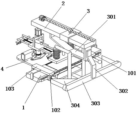
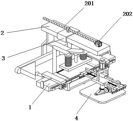
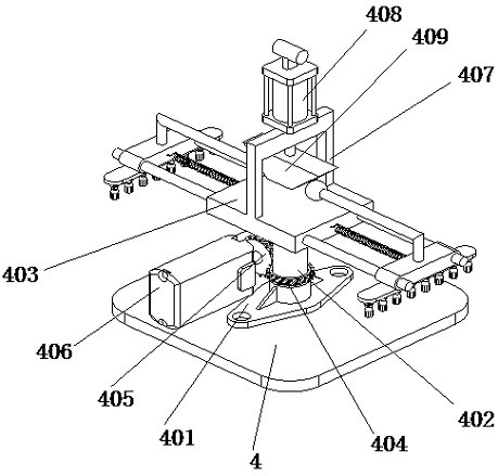
The invention discloses an automobile plate spring production lug rolling device facilitating stress relief, and belongs to the field of plate spring machining. The automobile plate spring production lug rolling device comprises a base table plate, a concave notch is formed in the middle of the base table plate, a linear propelling mechanism and a delay propelling mechanism are arranged on a linkage frame, and a material changing table is fixedly installed on one side of the base table plate; a plane shaft seat is fixedly installed at the top end of the material changing table, a center column is inserted into the plane shaft seat in a penetrating mode, the center column is rotationally connected with the plane shaft seat, a twisting table is fixedly installed at the top end of the center column, a material carrying mechanism is arranged at the top end of the twisting table, and an angle positioning assembly is arranged on the center column. An electromagnet is powered on to attract a plate spring, then a servo motor drives a center column and a torsion table to rotate by 180 degrees through an oblique angle gear set, a pressure air cylinder drives a conical block to fall down, the conical block expands and separates two feeding sliding blocks towards the two sides through a bending frame and an expansion ball, and the limitation of narrow machine tool operation space is eliminated; and the effect of automatic feeding and discharging is achieved.

Description

technical field [0001] The invention relates to the field of leaf spring processing, in particular to a rolling lug device for automobile leaf spring production which is convenient for stress relief. Background technique [0002] With the development of industrial technology, the development of modern automobile manufacturing technology has become more and more perfect. The core components in the manufacture of leaf springs and leaf springs require relatively high precision. The two ends of the plate spring are rolled, and the weight of the plate spring is relatively large, so the plate spring is more laborious when loading or unloading; [0003] The ear rolling operation of the leaf spring requires multiple process steps. After each processing of the leaf spring, the station needs to be replaced again for the next operation, which wastes time and manpower, thus increasing the processing cost. SUMMARY OF THE INVENTION [0004] The purpose of the present invention is to ai...

Claims


Application Information

Patent Timeline
IPC IPC(8): B21D11/10B21D11/22B21D43/00
CPCB21D11/10B21D11/22B21D43/003Y02P70/10
Inventor 卢霆李岗陈方清
Owner 湖南飞桥汽车板簧有限公司
Learn More