Submersible pump silt prevention device for river pond

A submersible pump and anti-sediment technology, which is applied to pump devices, parts of pumping devices for elastic fluids, pumps, etc., can solve the problem of increased work intensity, reduced water pumping function of submersible pumps, and inability to adjust the posture of submersible pumps and other problems to achieve the effect of increasing the service life and automatically removing sundries and aquatic plants

Inactive Publication Date: 2022-05-13
徐州上欧流体科技研究院有限公司
View PDF0 Cites 0 Cited by
  • Summary
  • Abstract
  • Description
  • Claims
  • Application Information

AI Technical Summary

Problems solved by technology

[0004] In order to solve the above technical problems, a kind of anti-sediment device for submersible pumps for rivers and ponds is provided. This technical solution solves the problem that the existing submersible pumps proposed in the above background technology are easy to absorb aquatic plants when pumping water in ponds or rivers. With sediment, it is necessary for the staff to take the submersible pump out of the river or pond for cleaning. It is impossible to automatically remove the water plants and sediment at the water inlet of the submersible pump when pumping water, which leads to the decline of the pumping function of the submersible pump and increases the work intensity. And when the existing submersible pump pumps water, the submersible pump usually lies flat on the bottom of the river or pond, and the posture of the submersible pump at the bottom of the water cannot be adjusted. Problems that occur when sediment enters the water inlet of the submersible pump and is blocked by aquatic plants

Method used


Image

  • Submersible pump silt prevention device for river pond
  • Submersible pump silt prevention device for river pond
  • Submersible pump silt prevention device for river pond

Examples


Embodiment 1

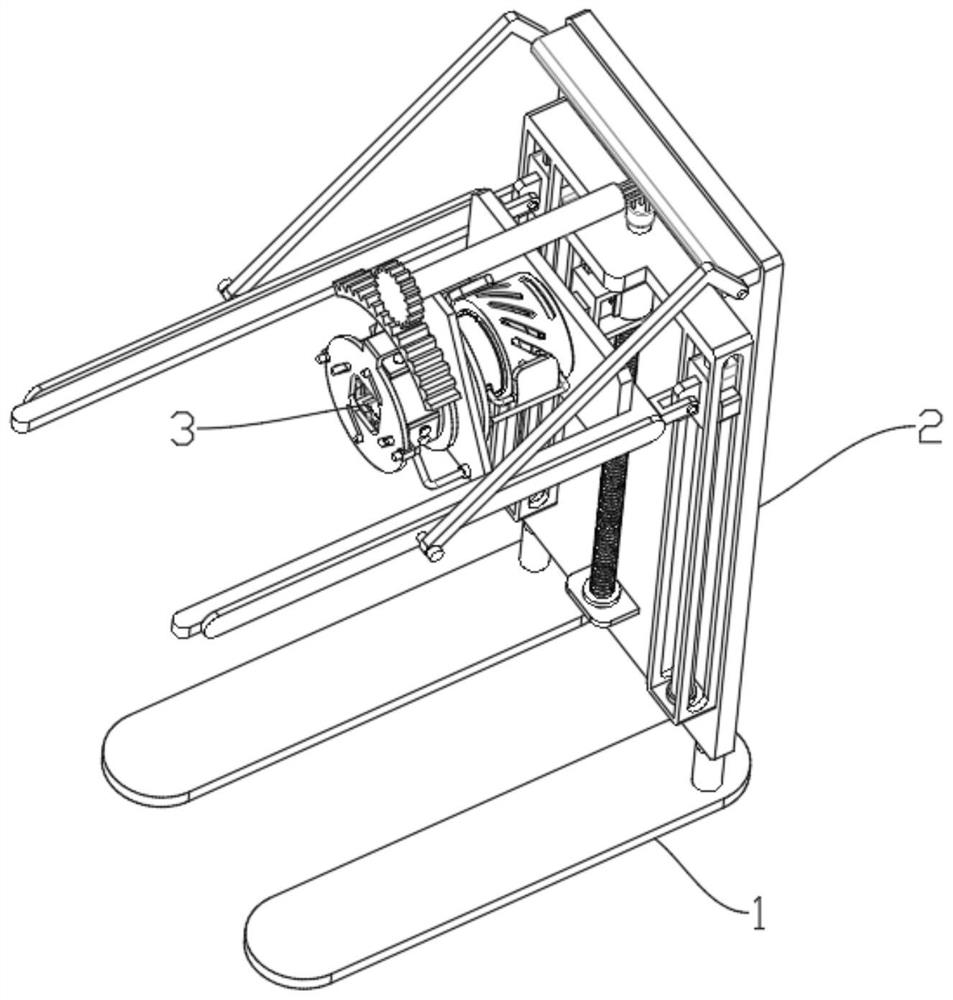
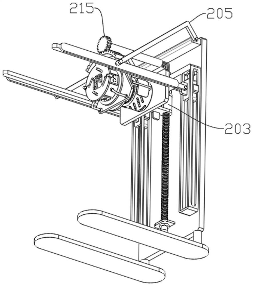
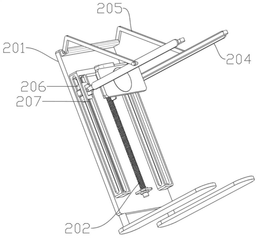
[0038] Please refer to figure 2 and image 3 and Figure 4 and Figure 5 and Image 6 and Figure 7 As shown, a submersible pump anti-sediment device for rivers and ponds includes a gravity base 1, the left end of the gravity base 1 is provided with a placement angle adjustment mechanism 2, and the left end of the placement angle adjustment mechanism 2 is provided with a docking filter mechanism 3, placed The angle adjustment mechanism 2 includes a mounting plate 201, a driving threaded rod 202, an internal threaded rotary sleeve 203, a driving frame plate 204, and a supporting curved rod 205. The middle end of the mounting plate 201 is rotationally connected with a driving threaded rod 202. There is an internal thread swivel 203, the right end of the internal thread swivel 203 is rotatably connected with a drive frame 204, the front and rear ends of the drive frame 204 are rotatably connected with a support bending rod 205, and the left end of the support bending rod 205 i...

Embodiment 2

[0041] Please refer to Figure 8 and Figure 9 and Figure 10 and Figure 11 and Figure 12 and Figure 13 and Figure 14 As shown, the docking filter mechanism 3 includes a filter cylinder 301, a high-pressure injection cylinder 302, a rubber extrusion disc 303, a protruding toggle plate 304, a slope chute disc 305, a return spring 306, and a power shaft 307. The left end surface of the drive frame plate 204 is fixedly connected with a filter cylinder 301, the inner surface of the lower end of the filter cylinder 301 is fixedly connected with a high-pressure injection cylinder 302, and the inner surface of the upper end of the high-pressure injection cylinder 302 is slidingly connected with a rubber extrusion circular plate 303, and the rubber extrusion The upper end of the pressure circular plate 303 is fixedly connected with a protruding toggle plate 304, and the middle end of the protruding toggle plate 304 is slidably connected with a power shaft 307, and the middle ...

Embodiment 3

[0044] Please refer to Figure 1 to Figure 14 As shown, a submersible pump anti-sediment device for rivers and ponds includes a gravity base 1, the left end of the gravity base 1 is provided with a placement angle adjustment mechanism 2, and the left end of the placement angle adjustment mechanism 2 is provided with a docking filter mechanism 3, placed The angle adjustment mechanism 2 includes a mounting plate 201, a driving threaded rod 202, an internal threaded rotary sleeve 203, a driving frame plate 204, and a supporting curved rod 205. The middle end of the mounting plate 201 is rotationally connected with a driving threaded rod 202. There is an internal thread swivel 203, the right end of the internal thread swivel 203 is rotatably connected with a drive frame 204, the front and rear ends of the drive frame 204 are rotatably connected with a support bending rod 205, and the left end of the support bending rod 205 is rotatably connected to the upper end of the mounting pla...


PUM


Abstract

A placement angle adjusting mechanism comprises a mounting plate, a driving threaded rod, an internal thread rotating sleeve, a driving frame plate and a supporting bent rod, the middle end of the mounting plate is rotationally connected with the driving threaded rod, and the upper end of the driving threaded rod is in threaded connection with the internal thread rotating sleeve; the right end of the internal thread rotating sleeve is rotationally connected with a driving frame plate, the front end and the rear end of the driving frame plate are rotationally connected with supporting bent rods, the left ends of the supporting bent rods are rotationally connected to the upper end of the mounting plate, and the left end of the driving frame plate is rotationally connected with a sliding sleeve. When the internal thread rotating sleeve moves upwards, the internal thread rotating sleeve drives the left end of the driving frame plate to move upwards, the right end of the driving frame plate is supported to be flush with the left end through the supporting bent rod, at the moment, the driving frame plate is converted into a transverse flat state from a vertical state, and a water inlet in the bottom end of the submersible pump is lifted.

Description

technical field [0001] The invention relates to the field of submersible pumps, in particular to a sediment prevention device for submersible pumps used in rivers and ponds. Background technique [0002] Submersible pump is an important equipment for deep well water extraction. When in use, the whole unit dives into the water and extracts groundwater to the surface. It is used for domestic water, mine rescue, industrial cooling, farmland irrigation, seawater lifting, ship loading, and fountain landscape. [0003] When existing submersible pumps are used to pump water in ponds or rivers, water plants and sediment are easily adsorbed at the water inlet, which requires staff to take the submersible pump out of the river or pond for cleaning, and cannot automatically clean the water at the water inlet of the submersible pump. Removal of aquatic plants and sediment will lead to a decline in the pumping function of the submersible pump and increase the working intensity. When the...

Claims


Application Information

Patent Timeline
Patent Type & Authority Applications(China)
IPC IPC(8): F04D29/00F04D29/62F04D15/00F04D29/70F04D29/66F04D13/08
CPCF04D29/007F04D29/628F04D15/00F04D29/708F04D13/08F04D29/669
Inventor 陈思蒙
Owner 徐州上欧流体科技研究院有限公司
Why Eureka
Try Eureka