Eureka AIR delivers breakthrough ideas for toughest innovation challenges, trusted by R&D personnel around the world.

Method for rapidly measuring permeability on well drilling and logging site

A technology for rapid measurement and permeability, applied in permeability/surface area analysis, cleaning methods using gas flow, cleaning methods and utensils, etc., can solve problems that cannot be well applied to outdoor workplaces, and achieve a high degree of automation , simple operation and high degree of integration

Pending Publication Date: 2022-05-13
青岛中石大教育发展有限公司
View PDF0 Cites 0 Cited by
  • Summary
  • Abstract
  • Description
  • Claims
  • Application Information

AI Technical Summary

Problems solved by technology

Usually, the plunger samples from the coring wells are taken back to the laboratory for cleaning and measurement, but in some special occasions it is necessary to quickly measure the permeability on the spot. In recent years, some domestic scholars have begun to introduce some new permeability testing methods. However, these methods or instruments are limited by the environment, and cannot be well applied to outdoor workplaces.

Method used


Image

  • Method for rapidly measuring permeability on well drilling and logging site
  • Method for rapidly measuring permeability on well drilling and logging site
  • Method for rapidly measuring permeability on well drilling and logging site

Examples


Embodiment 1

[0047] A method for rapid determination of permeability at the drilling and logging site, the method uses a device for rapid determination of permeability at the drilling logging site, the device includes a superlidge, a box, a control system, a gas supply system, a power supply system, a process system equipment and a simple foldable operating platform, the bottom of the box is provided with a tool sponge groove, each system and components are embedded in the corresponding groove and fixed by snapping or jaw, the operation platform and the top of the side wall of the box are connected by a hinge, and the operating platform can be folded into the box;

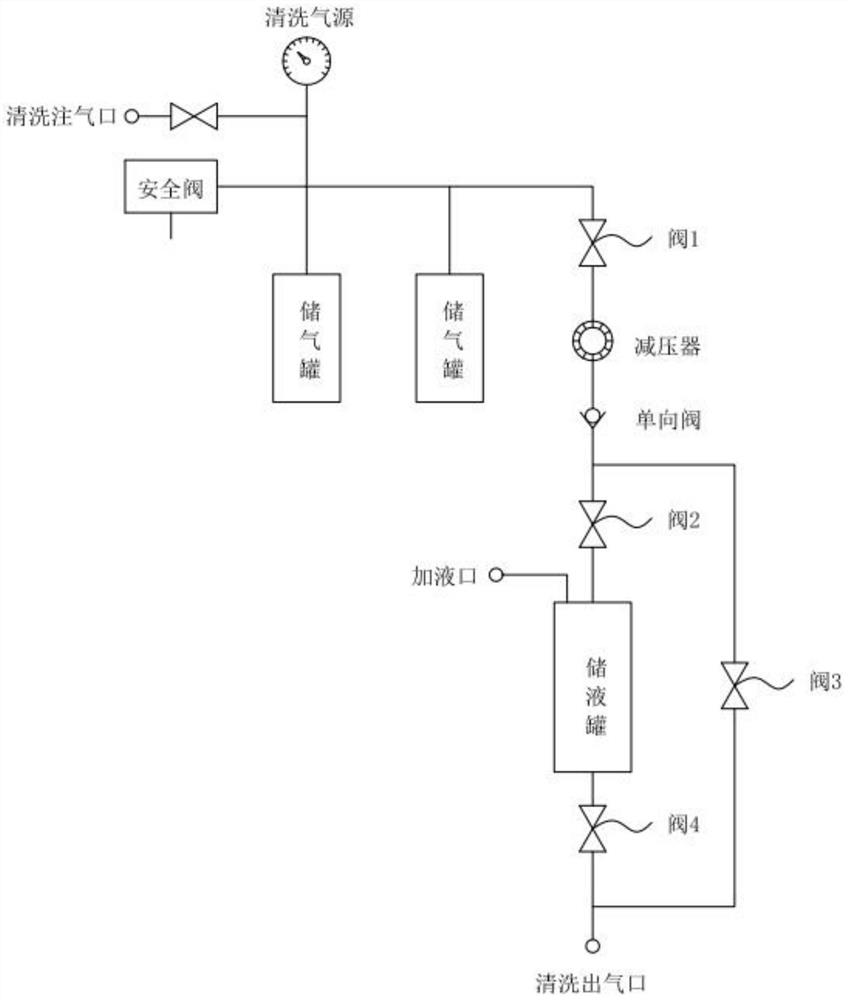
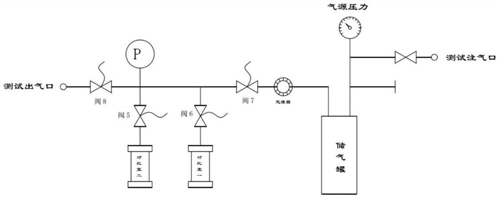
[0048] The gas supply system is divided into test gas tanks and cleaning gas tanks, test gas tanks and cleaning gas tanks are equipped with safety vent valves, and equipped with outdoor inflation pumps;

[0049]The process system equipment includes a cleaning system and a test system, the cleaning system includes an organic solven...

Embodiment 2

[0079] The method of rapid cleaning of the sample is similar to Example 1. When the sample is more oily and the cleaning is not clean, the sample can be placed in the core clamping device for testing.

[0080] The core clamping device includes an arc test probe, a pressure plate, a V-shaped positioning block and a fixed support; the arc test probe is located in the uppermost part of the clamping device, the arc surface test probe uses arc-shaped contacts at the top, the upper left side is provided with a lock switch, and the locking switch is provided with an inlet joint; the pressure plate is connected below the arc test probe, and the fixed support is connected below the pressure plate; the middle of the fixed support is provided with a groove that matches the V-type positioning block, the V-shaped positioning block is placed in the groove of the fixed support, and the compression spring is installed below the V-shaped positioning block. Can make the V-shaped positioning block m...


PUM


Abstract

According to the method for rapidly measuring the permeability in the well drilling and well logging site, the cleaning function is achieved, the cambered surface probe is used for testing the gas permeability of the sample, and the requirement for rapidly measuring the permeability after in-situ cleaning is conducted on the arc surface of the rock core in the well drilling and well logging site is met. In order to measure the permeability of a cylindrical rock sample rapidly on a well drilling and logging site, a test method is designed based on a gas point type diffusion principle. According to the method, the sample can be directly measured, and the test can be carried out after the sample is cleaned. The method disclosed by the invention is accurate in test and good in repeatability, and can be used for quickly carrying out work under simple and crude conditions on site.

Description

Technical field [0001] The present invention belongs to the field of reservoir development physical property evaluation technology, in particular to a method for rapid determination of permeability at the drilling and logging site. Background [0002] Permeability is an important parameter to describe the physical properties of reservoir rocks. It influences reservoir engineers' approach to oilfield extraction plans. Usually the situation is to take the core well plunger sample back to the laboratory for cleaning and determination, but some special occasions need to be quickly measured on the spot, in recent years, some scholars in China have begun to introduce some new permeability test methods, but these methods or instruments are limited by the environment, can not be well applied to outdoor work. Therefore, it is necessary to design a rapid measurement permeability test method for drilling and logging sites, which can be quickly tested on site. Contents of the Invention [...

Claims


Application Information

Patent Timeline
Patent Type & Authority Applications(China)
IPC IPC(8): G01N15/08G01N1/34B08B5/02
CPCG01N15/0826G01N15/0806G01N1/34B08B5/02
Inventor 孟虎邵东亮向军赵希春刘冬冬谢长春王建强
Owner 青岛中石大教育发展有限公司
Why Eureka
Eureka Blog
Learn More