
High-voltage battery having plurality of battery modules and heat sink

A high-voltage battery, battery module technology, applied in the direction of secondary batteries, battery pack components, circuits, etc., to achieve the effect of simple manufacturing

Pending Publication Date: 2022-05-13
DR ING H C F PORSCHE AG
View PDF3 Cites 0 Cited by
  • Summary
  • Abstract
  • Description
  • Claims
  • Application Information

AI Technical Summary

Problems solved by technology

This entails a huge construction, installation and cost outlay

Method used


Image

  • High-voltage battery having plurality of battery modules and heat sink
  • High-voltage battery having plurality of battery modules and heat sink
  • High-voltage battery having plurality of battery modules and heat sink

Examples


Embodiment Construction

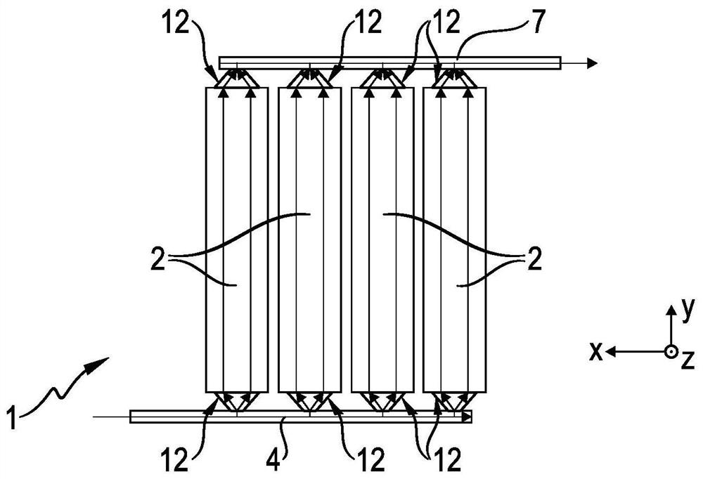
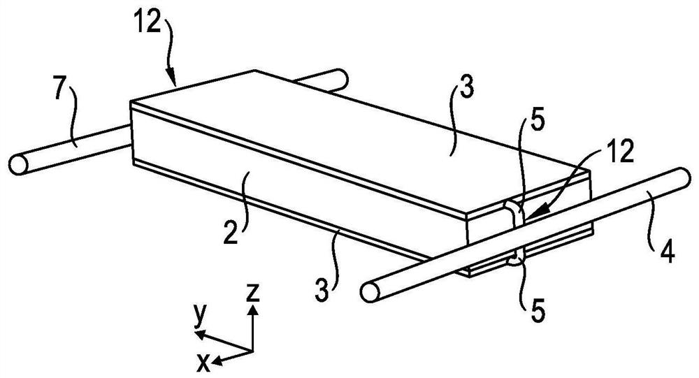
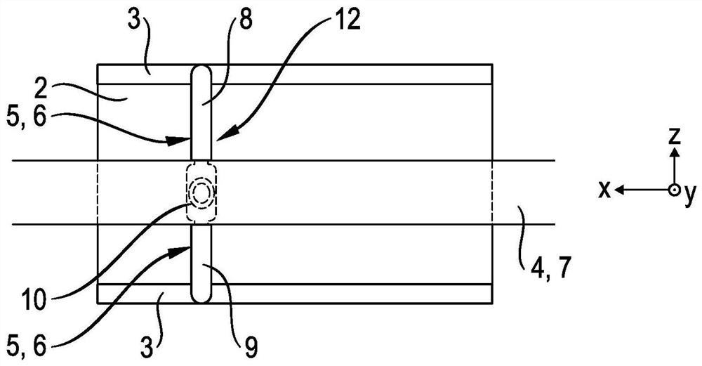
[0030] exist Figures 1 to 4 A first exemplary embodiment of the components of the high-voltage battery 1 that are relevant to the invention is shown in . A high-voltage battery 1 installed in a vehicle, for example a passenger motor vehicle, has: a plurality, in particular four battery modules 2; a cooling body 3 for conducting coolant for cooling the battery modules 2; A coolant supply line 4 supplied to the cooling body 3 via a supply connection 5 ; and a discharge connection 6 for discharging coolant from the cooling body 3 to a coolant discharge line 7 . In this case, the components according to reference numerals 3 to 7 form cooling components.

[0031] A corresponding battery module 2 has a plurality of battery cells, not shown. The battery module 2 is designed in the shape of a cuboid, wherein the sides of the cuboid extend in the vehicle longitudinal direction (forward travel direction) x, the vehicle transverse direction y and the vehicle height direction z. The c...


PUM


Abstract

The invention relates to a high-voltage battery (1), comprising: a plurality of battery modules (2); a coolant-conducting cooling body (3) for cooling the battery modules (2); a coolant supply line (4) for supplying coolant to the cooling bodies (3) via a supply connection (5); and a discharge connection (6) for discharging coolant from the cooling bodies (3) to a coolant discharge line (7). In such a high-voltage battery, it is proposed according to the invention that the supply connections (5) and the discharge connections (6) each form a coolant distributor (12), the respective coolant distributor (12) being attached to the cooling body (3) of the respective battery module (2).

Description

technical field [0001] The invention relates to a high-voltage battery having: a plurality of battery modules; a cooling body conducting coolant for cooling the battery modules; a cooling unit for supplying coolant to the cooling bodies via supply connections coolant supply lines; and discharge connections for discharging coolant from the cooling bodies to the coolant discharge lines. Background technique [0002] According to the prior art, the high-voltage battery in fully or partially electrically driven vehicles is cooled by means of a coolant, in particular a liquid. [0003] A high-voltage battery of the type mentioned at the outset is known from DE 10 2009 013 651 A1. In the case of the high-voltage battery, a heat sink is arranged in each case between adjacent battery modules. The respective cooling body is connected to the coolant supply line via the supply connection assigned to the flow limiting element. A coolant discharge line is arranged in the region of tha...

Claims


Application Information

Patent Timeline
Patent Type & Authority Applications(China)
IPC IPC(8): H01M10/613H01M10/625H01M10/6568
CPCH01M10/613H01M10/625H01M10/6568H01M50/204H01M10/6567H01M10/6557Y02E60/10H01M10/6551
Inventor P·克尔纳S·穆斯图菲C·沃尔克默D·席贝尔I·福格尔A·斯塔尔切夫斯基
Owner DR ING H C F PORSCHE AG
Learn More