Battery cell module and manufacturing method thereof
A cell module and manufacturing method technology, applied to battery pack parts, circuits, electrical components, etc., can solve problems such as misalignment of positioning holes for charging and discharging performance of battery systems, small influence of cell welding area, etc., to avoid poor welding , The effect of increasing the welding area and avoiding the problem of wrong holes
- Summary
- Abstract
- Description
- Claims
- Application Information
AI Technical Summary
Problems solved by technology
Method used
Image

Examples
Embodiment 1
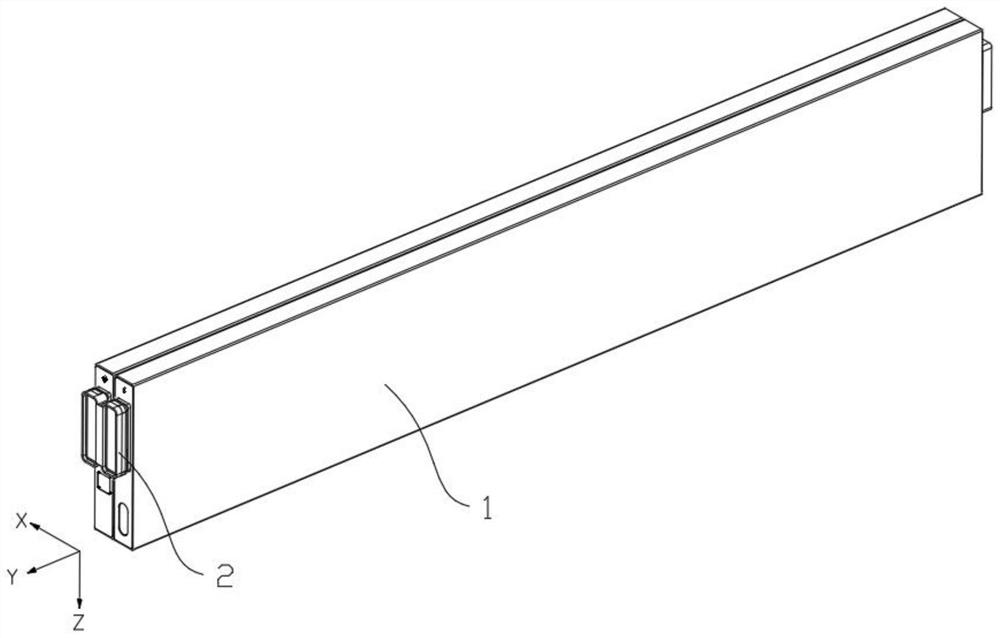
[0046] This embodiment provides a battery module, such as Figure 1-Figure 3 As shown, the battery module includes two battery cells 1 and bus bars 2 arranged along the X-axis direction. It should be noted that the number of battery cells 1 is not limited to two, and a corresponding number can be set according to requirements.
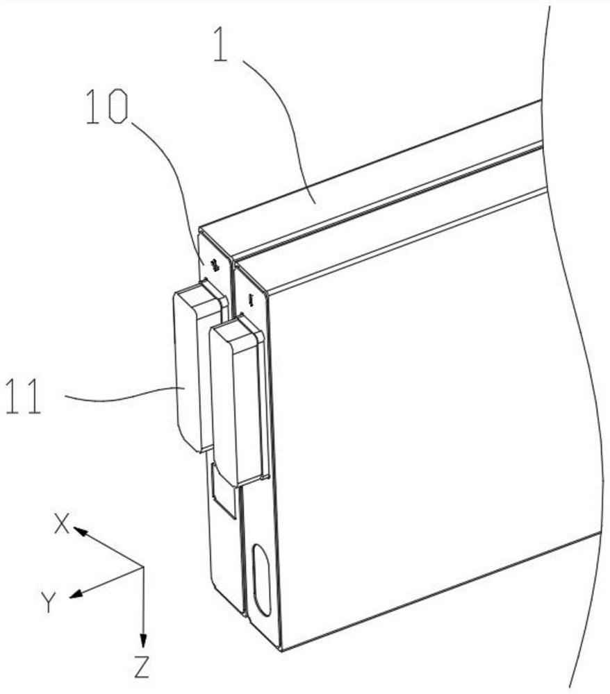
[0047] The battery cell 1 is provided with a pole mounting surface 10 , and poles 11 are provided on the pole mounting surface 10 , and the poles 11 on the pole mounting surfaces 10 on the same side of two adjacent battery cells 1 are spaced apart from each other.
[0048] In this embodiment, the poles 11 on the same side of the two battery cells 1 have opposite electrodes, so that the two battery cells 1 of the battery module are connected in series.
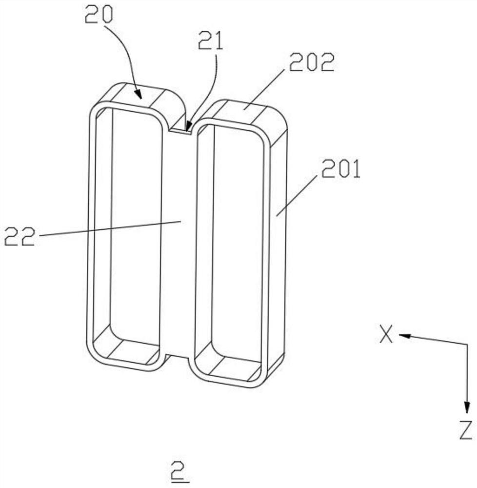
[0049] The bus bar 2 is provided with two surrounding structures 20 arranged along the X-axis direction, and a barrier part 21 is provided between the two surrounding structures 20, wherein the surroun...
Embodiment 2
[0063] This embodiment provides a battery module, such as figure 1 , figure 2 and Figure 4 As shown, the battery cell includes two battery cells 1 and busbars 2 arranged along the X-axis direction.
[0064] The battery cell 1 is provided with a pole installation surface 10 , and poles 11 are provided on the pole installation surface 10 , and the poles 11 on the pole installation surfaces 10 of two adjacent battery cells 1 are spaced apart from each other.
[0065] In this embodiment, the poles 11 on the same side of the two battery cells 1 have the same electrodes, so that the two battery cells 1 of the battery module are connected in parallel.
[0066] The bus bar 2 is provided with two surrounding structures 20 arranged along the X-axis direction, and a barrier part 21 is provided between the two surrounding structures 20, wherein the surrounding structures 20 are sleeved on the pole 11 in a one-to-one correspondence , The barrier portion 21 is disposed between two adja...
Embodiment 3
[0079] This embodiment provides a method for manufacturing a cell module, which is used to manufacture the cell module of Embodiment 1 or Embodiment 2. see Figure 1-Figure 4 , the method includes the following steps:
[0080] S100 , align each surrounding structure 20 of the bus bar 2 with the pole 11 of each battery cell 1 . It can be understood that the surrounding structure 20 is opposite to the pole 11 along the Y-axis direction.
[0081] S200, sleeve the surrounding structures 20 on the pole 11 in a one-to-one correspondence.
[0082] S300 , welding along the circumference of the enclosure structure 20 .
[0083] It should be noted that welding can be performed along the entire perimeter of the enclosure structure 20, or along a part of the perimeter of the enclosure structure 20, such as along a wide side and a long side of the enclosure structure 20. welding.
PUM
| Property | Measurement | Unit |
|---|---|---|
| Length | aaaaa | aaaaa |
Abstract
Description
Claims
Application Information
 - Generate Ideas
- Intellectual Property
- Life Sciences
- Materials
- Tech Scout
- Unparalleled Data Quality
- Higher Quality Content
- 60% Fewer Hallucinations
Browse by: Latest US Patents, China's latest patents, Technical Efficacy Thesaurus, Application Domain, Technology Topic, Popular Technical Reports.
© 2025 PatSnap. All rights reserved.Legal|Privacy policy|Modern Slavery Act Transparency Statement|Sitemap|About US| Contact US: help@patsnap.com