An optical module adjustment method with temperature compensation
An adjustment method and temperature compensation technology, applied in the field of optical communication, can solve the problems of optical power and temperature error of extinction ratio, and achieve the effect of accurate measurement and adjustment
- Summary
- Abstract
- Description
- Claims
- Application Information
AI Technical Summary
Problems solved by technology
Method used
Image

Examples
Embodiment 1
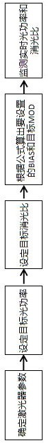
[0035] This embodiment proposes an optical module adjustment method with temperature compensation, which is used to control the optical power and extinction ratio of the optical module, such as figure 1 shown, including the following steps:
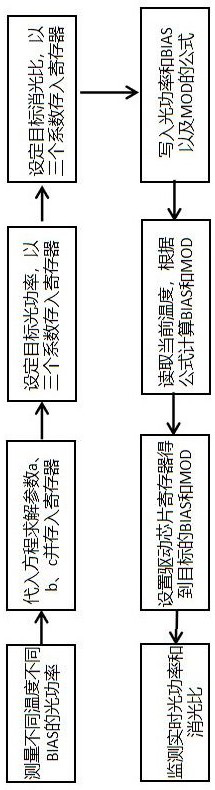
[0036] Step 1: Use the three intrinsic parameters of the laser as a measurement factor to describe the relationship between the corresponding luminous average power P, extinction ratio ER, laser bias current I and laser modulation current M at different temperatures t; the three intrinsic parameters Including: the slope a of the laser luminous efficiency with temperature, the loss b of the overall optical path coupling of the laser and the original luminous efficiency of the laser c;
[0037] Step 2: Calculate and measure the specific laser luminous efficiency slope a of the laser in actual use as a function of temperature, the loss b of the overall optical path coupling of the laser, and the original luminous efficiency of the laser c; ...
Embodiment 2
[0041] This embodiment is based on the above-mentioned Embodiment 1, in order to better realize the present invention, further, the step 1:
[0042] (1) Taking the slope a of the luminous efficiency of the laser with temperature, the loss b of the overall optical path coupling of the laser and the original luminous efficiency of the laser c as the measuring factors, establish a relationship about the average luminous power P, the specific relationship is as follows:
[0043] ;
[0044] In the formula, P is the average luminous power, a is the slope of the laser luminous efficiency with temperature, b is the loss of the overall optical path coupling of the laser, c is the original luminous efficiency of the laser, I is the laser bias current, and t is the specific temperature corresponding to , M is the laser modulation current.
[0045] (2) Using the slope a of the luminous efficiency of the laser with temperature, the loss b of the overall optical path coupling of the lase...
Embodiment 3
[0056] This embodiment is based on any one of the above-mentioned embodiments 1-2, in order to better realize the present invention, further, the specific operation of the step 2 is:
[0057] Step 2.1: For the actual laser, select three different temperature points; the interval between the selected temperature points is greater than 3°C.
[0058] Step 2.3: Provide the laser with different laser bias currents I and do not provide the laser modulation current M when three different temperature points correspond;
[0059] Step 2.3: Measure the average luminous power P of the laser at three temperature points;
[0060] Step 2.4: According to the relationship described in Step 1, reversely obtain the slope a of the laser luminous efficiency of the laser as a function of temperature, the loss b of the overall optical path coupling of the laser, and the original luminous efficiency of the laser c.
[0061] The other parts of this embodiment are the same as any of the above-mentione...
PUM
 Abstract
Description
Claims
Application Information
 - R&D
- Intellectual Property
- Life Sciences
- Materials
- Tech Scout
- Unparalleled Data Quality
- Higher Quality Content
- 60% Fewer Hallucinations
Browse by: Latest US Patents, China's latest patents, Technical Efficacy Thesaurus, Application Domain, Technology Topic, Popular Technical Reports.
© 2025 PatSnap. All rights reserved.Legal|Privacy policy|Modern Slavery Act Transparency Statement|Sitemap|About US| Contact US: help@patsnap.com