Rotor structure of external rotor motor and external rotor motor

A technology of external rotor motor and rotor structure, applied in the direction of electromechanical devices, electrical components, electric components, etc., can solve the problems of increasing the risk of permanent magnet demagnetization, increasing the loss of coil winding, and increasing the current of coil winding, so as to reduce the risk of demagnetization and reduce the Coil winding loss, the effect of increasing the operating speed

Active Publication Date: 2022-05-13
ZHONGSHAN BROAD OCEAN
View PDF5 Cites 0 Cited by
  • Summary
  • Abstract
  • Description
  • Claims
  • Application Information

AI Technical Summary

Problems solved by technology

[0005] The purpose of the present invention is to provide a rotor structure of an external rotor motor and an external rotor motor, which can solve the problem of increasing the D-axis demagnetization current to weaken the magnetic field to increase the speed of the motor in the prior art, which leads to an increase in the coil winding current and an additional coil Winding losses, technical issues that reduce the efficiency of the motor and increase the risk of demagnetization of the permanent magnets

Method used


Image

  • Rotor structure of external rotor motor and external rotor motor
  • Rotor structure of external rotor motor and external rotor motor
  • Rotor structure of external rotor motor and external rotor motor

Examples


Embodiment 1

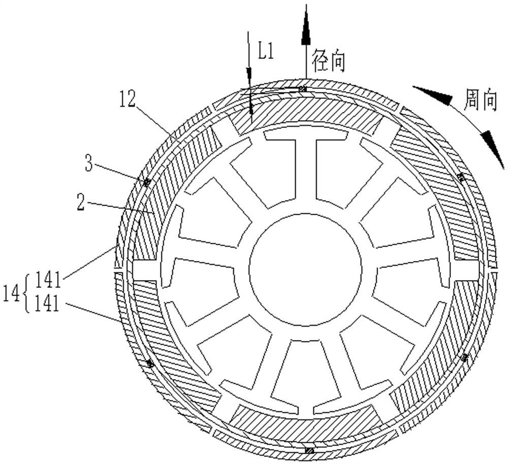
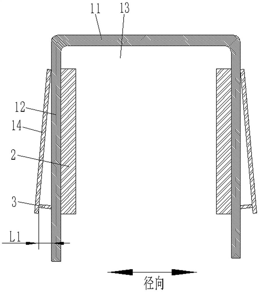
[0038] Such as figure 1 , figure 2 and image 3 As shown, this embodiment provides a rotor structure of an external rotor motor, including a rotor housing 1 and a number of permanent magnets 2. The rotor housing 1 includes an end plate 11 and a sleeve housing 12 extending from the edge of the end plate 11. The plate 11 and the sleeve shell 12 form a cavity 13, and several permanent magnets 2 are installed on the inner wall surface of the sleeve shell 12 at intervals in the circumferential direction. It is characterized in that: a movable shell 14 is installed on the outer surface of the sleeve shell 12. The casing 14 is movably installed on the outer wall of the sleeve casing 12, and the movable casing 14 is arranged radially outside the permanent magnet 2. When the rotor rotates at a speed exceeding a certain speed, the movable casing 14 moves radially to realize the effect of weakening the magnetic field and increasing the operating speed. Purpose, at high speed, without ...

Embodiment 2

[0046] Such as Figure 4As shown, this embodiment is further improved on the basis of Embodiment 1. The above-mentioned deformable connector 3 is connected to one end of the movable monomer 141, and the other end of the movable monomer 141 is hinged on the outer wall of the sleeve shell 12 ( hinge is not shown), when the rotor rotates beyond a certain speed, one end of the movable monomer 141 does not move, and the other end swings around the hinge, the deformable connector is deformed, and the deformation distance of the deformable connector is L1, so that the movable monomer 141 Radial movement is used to achieve the purpose of weakening the magnetic field and increasing the operating speed. At high speeds, there is no need to increase the D-axis field weakening current, reduce coil winding loss, improve motor efficiency, and reduce the risk of permanent magnet demagnetization.

Embodiment 3

[0048] Such as Figure 5 As shown, this embodiment is further improved on the basis of Embodiment 1. There are two movable casings 14 above, and the two movable casings 14 are arranged at intervals along the axial direction. It consists of movable units 141 on the outer wall, and each movable unit 141 is movably installed on the outer wall of the sleeve housing 12 .

[0049] A deformable connector 3 is provided between each movable monomer 141 and the sleeve shell 12, and the inner wall surface of the movable monomer 141 and the outer wall surface of the sleeve shell 12 are respectively fixedly connected to both ends of the deformable connector 3, when When the rotor rotates over a certain speed, the deformable connector 3 is deformed, and the deformation distance of the deformable connector is L1, so that the movable monomer 141 can move radially to achieve the purpose of weakening the magnetic field and increasing the operating speed. At high speed, there is no need to incre...


PUM


Abstract

The rotor structure comprises a rotor shell and a plurality of permanent magnets, the rotor shell comprises an end plate and a sleeve shell extending from the edge of the end plate, a cavity is defined by the end plate and the sleeve shell, and the permanent magnets are installed on the inner wall face of the sleeve shell at intervals in the circumferential direction. The permanent magnet motor is characterized in that a movable shell is installed on the outer surface of the sleeve shell, the movable shell is movably installed on the outer wall face of the sleeve shell, the movable shell is arranged on the radial outer side of the permanent magnet, and when the rotation speed of the rotor exceeds a certain rotating speed, the movable shell moves in the radial direction or the axial direction to achieve the purpose of increasing the running rotating speed through flux weakening; d-axis weak magnetic current does not need to be increased, the coil winding loss is reduced, the motor efficiency is improved, and the demagnetization risk of the permanent magnet can be reduced.

Description

technical field [0001] The invention relates to a rotor structure of an outer rotor motor and the outer rotor motor. Background technique [0002] The existing external rotor motor includes a rotating shaft, a stator assembly, an external rotor and a sleeve seat. The sleeve seat includes a bottom plate and a sleeve protruding upward from the middle of the bottom plate. Bearing chambers are opened at both ends of the sleeve, and the bearing chamber is installed There are bearings, the rotating shaft is located inside the sleeve and the two ends are respectively supported on the bearings. The outer rotor includes the casing sleeve and a number of permanent magnets installed on the inner wall of the casing sleeve. One end of the rotating shaft protrudes from the sleeve and The casing sleeve is installed and connected together, the stator assembly is nested and installed outside the sleeve, and the outer rotor is sleeved outside the stator assembly. [0003] The casing sleeve a...

Claims


Application Information

Patent Timeline
Patent Type & Authority Applications(China)
IPC IPC(8): H02K5/04H02K1/2791
CPCH02K5/04H02K1/2786
Inventor 关超
Owner ZHONGSHAN BROAD OCEAN
Why Eureka
Try Eureka