
Double-ball type self-resetting wave energy collecting device

A collection device and self-reset technology, applied in electromechanical devices, ocean energy power generation, machines/engines, etc., can solve the problems of increasing the production cost of the device, inefficient energy collection, and harsh waterproof performance of the device, so as to improve the efficiency of power generation, The effect of prolonging work efficiency and improving power generation efficiency

Pending Publication Date: 2022-05-13
JIANGSU UNIV OF SCI & TECH
View PDF0 Cites 0 Cited by
  • Summary
  • Abstract
  • Description
  • Claims
  • Application Information

AI Technical Summary

Problems solved by technology

The device realizes the energy harvesting of the device to a certain extent, but when the displacement applied by the wave to the device is parallel to the direction of the flexible cantilever beam or the angle is small, the elastic deformation of the cantilever beam will be very small, and the energy harvesting efficiency of the piezoelectric sheet will also increase. Being greatly affected, the single-channel energy harvesting that only relies on the piezoelectric sheet attached to the cantilever beam to collect energy is not efficient enough. At the same time, the single-layer design puts forward extremely strict requirements for the waterproof performance of the device, which increases the production cost of the device.

Method used


Image

  • Double-ball type self-resetting wave energy collecting device
  • Double-ball type self-resetting wave energy collecting device
  • Double-ball type self-resetting wave energy collecting device

Examples


Embodiment Construction

[0018] The technical solution of the present invention will be further described below in conjunction with the accompanying drawings.

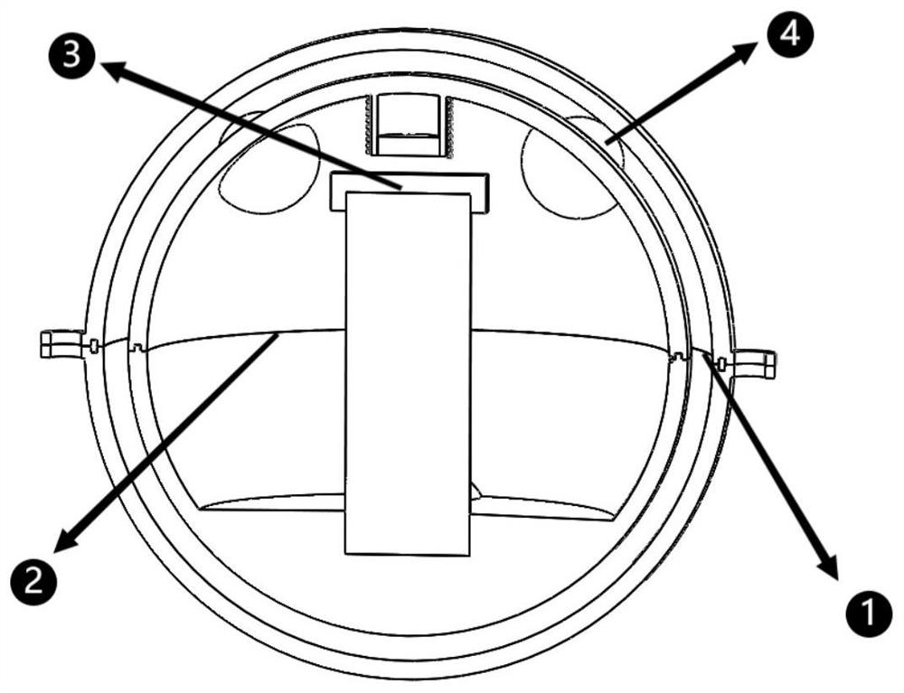
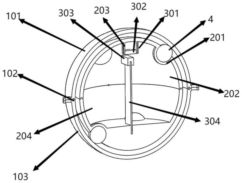
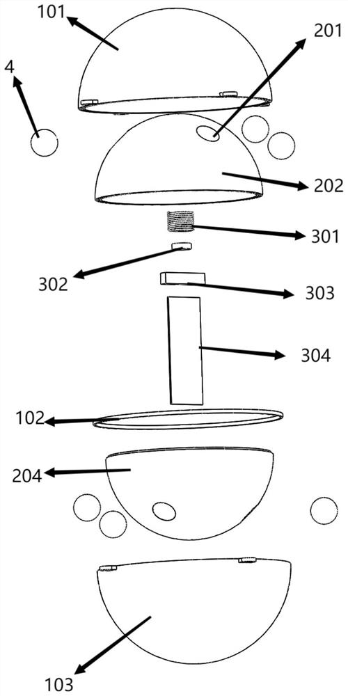
[0019] like Figure 1-6 In the shown embodiment, the present invention includes a protective shell 1, an eccentric inner spherical shell 2, a first energy harvesting mechanism 3, a second energy harvesting mechanism and a storage battery; wherein, the inner and outer walls of the protective shell 1 are spherical, and in other embodiments Among them, the outer surface of the protective shell 1 can also be set to other shapes; the inside of the protective shell 1 is provided with an eccentric inner spherical shell 2, and the outer surface of the eccentric inner spherical shell 2 is symmetrically provided with a spherical groove 201, and the spherical groove 201 is provided with a The universal ball 4 freely rotating in the spherical groove 201, the universal ball 4 abuts on the inner wall of the protective shell 1, as Image 6 As shown, in this...


PUM


Abstract

The invention discloses a double-ball type self-resetting wave energy collecting device which comprises a protective shell, an eccentric inner spherical shell with the gravity center not coincident with the sphere center is arranged in the protective shell, a first energy collecting mechanism and a second energy collecting mechanism are arranged in the eccentric inner spherical shell, and the first energy collecting mechanism comprises a cantilever beam made of a flexible material; the second energy collecting mechanism comprises a pipeline arranged on the eccentric inner spherical shell and a first permanent magnet arranged in the pipeline in a sliding mode, the pipeline is provided with a cantilever beam, a piezoelectric plate is attached to the cantilever beam, one end of the cantilever beam is fixedly connected with the inner wall of the eccentric inner spherical shell, and the other end of the cantilever beam is provided with a second permanent magnet playing a role of a mass block. The first permanent magnet and the second permanent magnet are opposite, the corresponding magnetic poles are the same, a coil is further arranged on the outer side of the pipeline, repulsion of the first permanent magnet and the second permanent magnet can prolong the vibration time of the cantilever beam, meanwhile, magnetic induction lines can be cut, power is generated through the Faraday effect, and compared with an energy collection device of a single-ball structure, the power generation efficiency is greatly improved.

Description

technical field [0001] The invention relates to a wave energy collection device, in particular to a wave energy collection device with high self-generating efficiency and continuous power supply. Background technique [0002] The total area of ​​oceans on the earth accounts for about 71% of the total surface area of ​​the earth. The oceans contain extremely rich resources and are the treasure house on which human beings rely for survival. Therefore, the importance of marine resource development has become increasingly prominent. Many countries have formulated corresponding ocean development strategies , seek to use marine technology as a guide to solve the problem of energy shortage and improve international competitiveness. The basis of development is observation. At present, marine environment observation mainly relies on various ocean observation equipment, fixed-point observation platform and mobile three-dimensional observation network to conduct marine environment obse...

Claims


Application Information

Patent Timeline
Patent Type & Authority Applications(China)
IPC IPC(8): H02N2/18H02K35/02F03B13/14
CPCH02N2/186H02K35/02F03B13/14Y02E10/30
Inventor 方记文范波李雪莹李冲王红茹吕明明王佳
Owner JIANGSU UNIV OF SCI & TECH
Learn More