
Electromagnetic energy protection module and radio frequency transceiving link based on same

A technology of electromagnetic energy and protection circuit, applied in the direction of reducing energy consumption, electrical components, advanced technology, etc., can solve the problems that the limiter is difficult to deal with energy impact, damage the sensitive parts of the receiving branch, and cannot enter the receiving branch, etc., to achieve The effect of controllable energy size, non-reciprocity, and convenient design

Active Publication Date: 2022-05-13
湖南雷远电子科技有限公司
View PDF11 Cites 0 Cited by
  • Summary
  • Abstract
  • Description
  • Claims
  • Application Information

AI Technical Summary

Problems solved by technology

When the energy flowing in from the antenna end is small, although the coupling degree of the coupling end is large, the total energy extracted is not enough to make the protection branch conduct. At this time, the energy received by the antenna can pass through the protection module with relatively low loss; When the energy is large, the total energy taken out from the coupling port is large, which can drive the protection branch to open. At this time, most of the energy is reflected and cannot enter the receiving branch, which will damage the sensitive parts of the receiving branch.
[0004] The design idea of ​​the existing protection module is based on the limiter, which can only be used for the protection of the receiving branch, and as the electromagnetic energy radiated in space becomes larger and larger, it is difficult for the simple limiter to deal with such a strong energy impact

Method used


Image

  • Electromagnetic energy protection module and radio frequency transceiving link based on same
  • Electromagnetic energy protection module and radio frequency transceiving link based on same
  • Electromagnetic energy protection module and radio frequency transceiving link based on same

Examples


Embodiment Construction

[0030] In order to make the purpose, technical solutions and advantages of the embodiments of the present invention more clear, the following will clearly illustrate the spirit of the disclosure of the present invention with the accompanying drawings and detailed descriptions. Anyone skilled in the art can understand the embodiments of the present invention Later, when it can be changed and modified by the technology taught in the content of the present invention, it does not depart from the spirit and scope of the content of the present invention. The exemplary embodiments and descriptions of the present invention are used to explain the present invention, but not to limit the present invention.

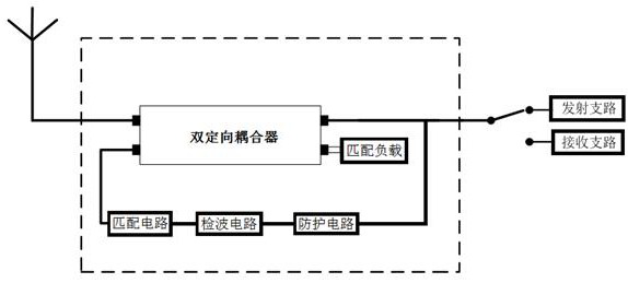
[0031] refer to figure 1 , an electromagnetic energy protection module provided in an embodiment includes a dual directional coupler, a detection circuit and a protection circuit.

[0032] The dual directional coupler is connected in the common channel for transmitting and receivin...


PUM


Abstract

The invention provides an electromagnetic energy protection module and a radio frequency transceiving link based on the electromagnetic energy protection module. The electromagnetic energy protection module comprises a bi-directional coupler, a detection circuit and a protection circuit, the bi-directional coupler comprises four ports, namely a first port, a second port, a third port and a fourth port, the first port is correspondingly connected with an antenna on the receiving and transmitting common channel, the second port is correspondingly connected with a transmitting branch or a receiving branch of the receiving and transmitting common channel, and the third port is correspondingly connected with a receiving branch of the receiving and transmitting common channel. A detection circuit and a protection circuit are connected between the third port and the second port, and the fourth port is connected with a matched load; the third port of the bi-directional coupler takes out the electromagnetic energy from the transmitting-receiving common channel and sends the electromagnetic energy to the detection circuit for detection, and when the electromagnetic energy taken out from the transmitting-receiving common channel by the third port of the bi-directional coupler reaches a set threshold value, the driving protection circuit is started after the electromagnetic energy is detected by the detection circuit. The device is based on transmitting and receiving shared channel electromagnetic protection and can be directly loaded between an antenna and equipment, so that strong electromagnetic reinforcement is completed.

Description

technical field [0001] The invention relates to the technical field of electromagnetic protection, in particular to an electromagnetic energy protection module and a radio frequency transceiver link based thereon. Background technique [0002] Strong electromagnetic energy attack has high energy intensity, high peak value, adjustable spectrum width, wide range of action, strong controllability, low restriction and high strike efficiency, and is favored by more and more military powers. favor. The entry of strong electromagnetic energy from the antenna can directly or indirectly weaken or even cause the command information system to be paralyzed, resulting in confusion in battlefield perception, disordered command coordination, and decreased effectiveness of frequency equipment, affecting and even misleading command decisions. The shared channel for transmitting and receiving at the back end of the antenna is the only way for strong electromagnetic energy. The traditional pr...

Claims


Application Information

Patent Timeline
Patent Type & Authority Applications(China)
IPC IPC(8): H04B1/10H04B1/12H04B1/40H04B1/44
CPCH04B1/109H04B1/123H04B1/44H04B1/40Y02D30/70
Inventor 孙伟柴进黄玲
Owner 湖南雷远电子科技有限公司
Learn More