Electromagnetic wave isolator based on magneto-optical medium

A magneto-optical medium and electromagnetic wave technology, applied in the electromagnetic field, can solve the problem of non-reciprocal dispersion, etc., and achieve the effect of simple structure and easy realization.

Pending Publication Date: 2018-10-12
NANJING FORESTRY UNIV
View PDF4 Cites 1 Cited by
  • Summary
  • Abstract
  • Description
  • Claims
  • Application Information

AI Technical Summary

Problems solved by technology

This invention is suitable for integrated electronic devices. By adjusting the arrangement period consistent with the results, it can have a good one-way conduction effect in a wide range of wave bands. However, this invention does not use the anisotropy of the material itself for light and electromagnetic waves. The non-reciprocal dispersion when it is incident on the boundary of two different media makes the electromagnetic wave have a single characteristic during transmission

Method used


Image

  • Electromagnetic wave isolator based on magneto-optical medium
  • Electromagnetic wave isolator based on magneto-optical medium
  • Electromagnetic wave isolator based on magneto-optical medium

Examples


Embodiment 1

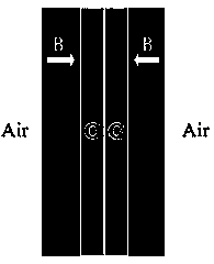
[0057] Embodiment 1: Select the thickness of the silicon dielectric layer and the electrogyromagnetic-optical dielectric layer to be d respectively 1 = 25mm, d 2 The structure model of =30mm is taken as an example, in the dielectric layers on both sides of the middle two layers, a forward magnetic field of 0.02T is added to the left electrogyromagnetic-optical material, and a reverse magnetic field of 0.02T is added to the right electrogyromagnetic-optic material. The relative permittivity of the electrocyclomagneto-optic on both sides is It changes with the applied frequency, the relative permeability is 1, the relative permittivity of the middle silicon dielectric layer is ε=2.07, and the relative permeability is 1, and then incident from the left and right sides of the structure at an incident angle of 30°.

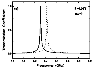
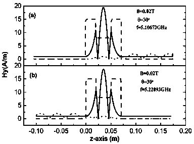
[0058] Depend on figure 2 It can be seen that the transmission coefficient varies with the frequency. The forward incident frequency is f=5.10673e14Hz, the transmi...

Embodiment 2

[0062] Embodiment 2: Select the thickness of the silicon dielectric layer and the electrogyromagnetic-optical dielectric layer to be d respectively 1 = 25mm, d 2 The structure model of =30mm is taken as an example, in the dielectric layers on both sides of the middle two layers, a forward magnetic field of 0.02T is added to the left electrogyromagnetic-optical material, and a reverse magnetic field of 0.02T is added to the right electrogyromagnetic-optical material. The relative permittivity of the magneto-optic materials on both sides is It changes with the incident frequency, the magnetic permeability is 1, the relative permittivity of the middle silicon dielectric layer is ε=2.07, and the relative magnetic permeability is 1, and then incident from the left and right sides of the structure at different incident angles. Figure 4 The incident angles are 30°, 45° and 60° respectively. The forward and reverse directions are the relationship between the transmission coefficien...

Embodiment 3

[0063] Embodiment 3: Select the thickness of the silicon dielectric layer and the electrogyromagnetic-optical dielectric layer to be d respectively 1 = 25mm, d 2 = 30mm structural model as an example, the relative permittivity of the middle silicon dielectric layer is ε=2.07, the relative permeability is 1, and the relative permittivity of the electric cyclotron magneto-optical materials on both sides is It varies with the incident frequency, the magnetic permeability is 1, and the incident angle is 30°. The left and right electrogyromagneto-optical materials in the dielectric layers on both sides of the middle two layers are respectively added with forward and reverse magnetic fields, and the magnitudes of the magnetic fields are 0.02T, 0.04T and 0.06T respectively. Figure 5 is the variation of the transmission coefficient with frequency under different external magnetic fields (the solid line represents the forward propagation, and the dotted line represents the reverse p...


PUM


Abstract

The invention discloses an electromagnetic wave isolator based on a magneto-optical medium. The electromagnetic wave isolator based on the magneto-optical medium includes four stacked medium layers, wherein the two middle medium layers are made of a normal medium material, the depths of the middle medium layers are d1, the medium layers at the two sides of the middle medium layers are made of a magneto-optical material, and the depths of the medium layers at the two sides of the middle medium layers are d2. According to the electromagnetic wave isolator based on the magneto-optical medium, thecharacteristics are adopted that electromagnetic parameters of the magneto-optical material have anisotropy along with change of the frequency of incident waves, and the magneto-optical material andan external magnetic field have specific relations, the nonreciprocity of the waves is achieved; an incident angle or the magnitude of the magnetic field is changed, then, frequency capable of passingthrough the structure is screened out, the single-direction optical propagation intensity is further improved, and the electromagnetic wave isolator based on the magneto-optical medium is simple in structure and easy to implement.

Description

technical field [0001] The invention belongs to the field of electromagnetic technology, in particular to an electromagnetic wave one-way device based on a magneto-optical medium. Background technique [0002] The electromagnetic wave one-way device is a device with one-way electromagnetic propagation characteristics produced by the incident one-dimensional layered structure magneto-optical medium material of electromagnetic wave. When the electromagnetic wave is incident on the boundary of two different magneto-optical media, it can form a non-reciprocal Optical surface plasmon wave (SPP). Due to the special electromagnetic parameters in the dielectric medium, the SPP wave excitation on the surface is non-reciprocal, which breaks the symmetry of electromagnetic wave propagation in time and space, and can realize the one-way electromagnetic wave propagation effect at the frequency of exciting the SPP state. . Since the magneto-optical material is an anisotropic material, t...

Claims


Application Information

Patent Timeline
Patent Type & Authority Applications(China)
IPC IPC(8): H01P1/32
CPCH01P1/32
Inventor 余观夏付晶晶骆敏杜文文吕一航
Owner NANJING FORESTRY UNIV
Why Eureka
Try Eureka