Anti-violence hemispherical monitoring camera with cleaning mechanism
A monitoring camera and cleaning mechanism technology, which is applied to the body of the camera, the cleaning method using tools, cleaning methods and utensils, etc., can solve the problems of installation and fixation, easy blind spots in the field of vision, and unclear shooting of the anti-violence hemispherical monitoring camera, etc. problem, to achieve the effect of improving the shooting clarity
- Summary
- Abstract
- Description
- Claims
- Application Information
AI Technical Summary
Problems solved by technology
Method used
Image
Examples
Embodiment 1
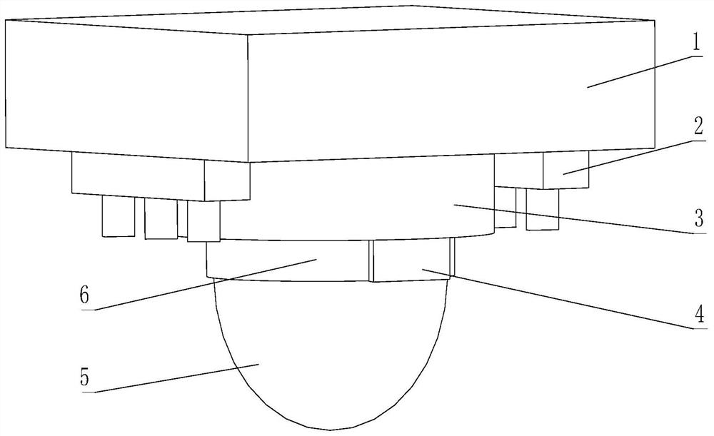
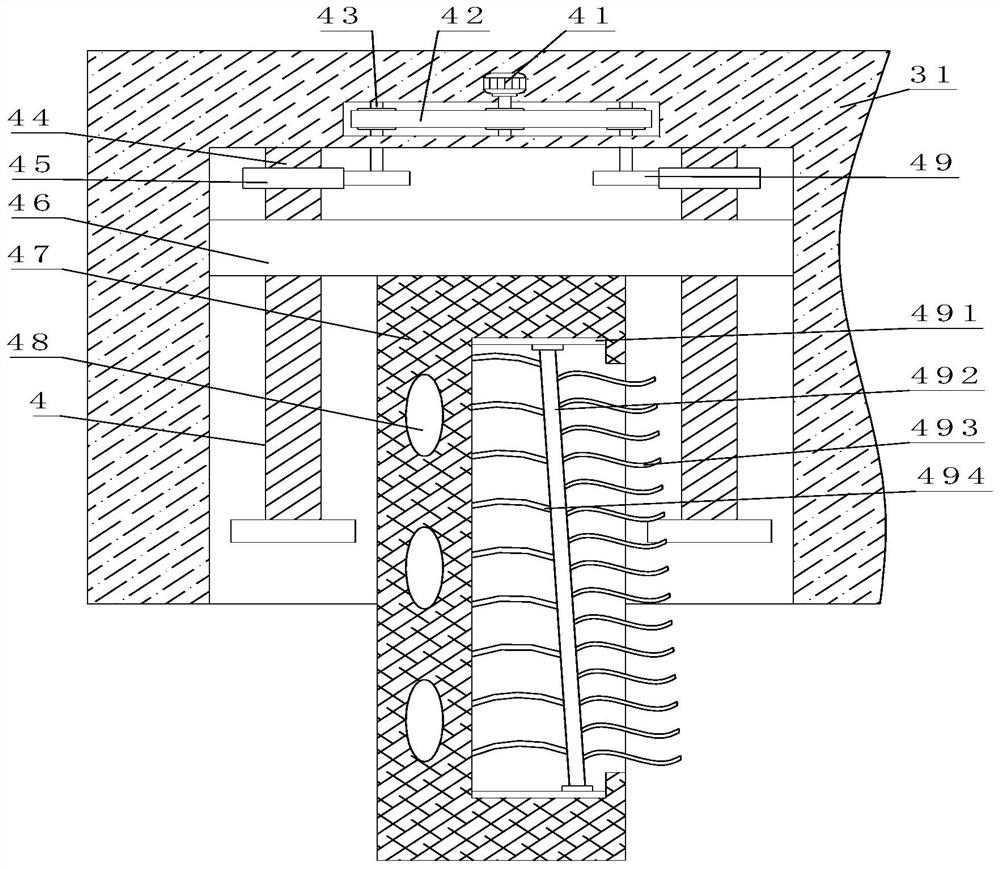
[0040] Such as Figure 1-6 As shown, the present invention provides a kind of anti-violence hemispherical monitoring camera with cleaning mechanism, comprises explosion-proof force hemispherical monitoring camera 5, and the top of explosion-proof force hemispheric monitoring camera 5 is provided with connecting base 6, and the top of connecting base 6 is provided with mounting base 3. The bottom of the mounting base 3 is provided with a cleaning mechanism 4, the top of the mounting base 3 is provided with a mounting plate 1, and the bottom of the mounting plate 1 is provided with a cooling mechanism 2. The cleaning mechanism 4 includes a threaded rod 44, and the surface of the threaded rod 44 is threaded. There is a lifting plate 46, the bottom of the lifting plate 46 is fixedly connected with a cleaning plate 47, the inside of the cleaning plate 47 is provided with an electromagnet 48, the inner wall of the cleaning plate 47 is provided with a slide rail 491, and the surface o...
Embodiment 2
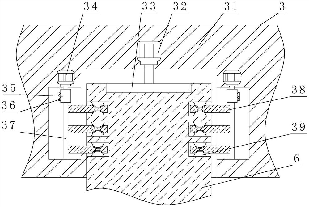
[0043] Such as Figure 1-6 As shown, on the basis of Embodiment 1, the present invention provides a technical solution: preferably, the installation base 3 includes a base body 31, and the inside of the base body 31 is provided with a No. 3 motor 32, and the output end of the No. 3 motor 32 extends to The inner cavity of the base body 31 is fixedly connected with a connecting plate 33, the inside of the base body 31 is provided with a No. 2 motor 34, the output end of the No. 2 motor 34 is fixedly connected with a No. 2 rotating rod 37, and the bottom of the No. 2 rotating rod 37 has a base The bottom of the cavity of the body 31 is movably connected, and the surface of the No. 2 turning rod 37 and the inner cavity of the base body 31 are fixedly connected with a runner 35. The surface of the runner 35 is lapped with a No. 2 transmission belt 36, and the second turning lever 37 The surface is fixedly connected with a fixed plate 38, the surface of the fixed plate 38 is lapped ...
Embodiment 3
[0046] Such as Figure 1-6 As shown, on the basis of Embodiment 1, the present invention provides a technical solution: preferably, the cooling mechanism 2 includes a cooling shell 21, and the top of the cooling shell 21 is movably connected with a third rotating rod 22, and the surface of the third rotating rod 22 The No. 2 bevel gear 25 is fixedly connected, and the top of the inner wall of the cooling shell 21 is provided with a double-headed motor 23. The output end of the double-headed motor 23 is fixedly connected with a No. 2 bevel gear 24, and the surface of the No. 1 bevel gear 24 is connected to the No. 2 bevel gear 25. The surface of the No. 3 rotating rod 22 is fixedly connected with the fan blade 26 under the No. 2 bevel gear 25. The inner wall side of the cooling shell 21 is fixedly connected with the water tank 27. The surface of the water tank 27 is provided with a cooling plate 291. The water tank 27 One side of the water pipe 28 is provided with a water pump ...
PUM
 Abstract
Description
Claims
Application Information
 - R&D
- Intellectual Property
- Life Sciences
- Materials
- Tech Scout
- Unparalleled Data Quality
- Higher Quality Content
- 60% Fewer Hallucinations
Browse by: Latest US Patents, China's latest patents, Technical Efficacy Thesaurus, Application Domain, Technology Topic, Popular Technical Reports.
© 2025 PatSnap. All rights reserved.Legal|Privacy policy|Modern Slavery Act Transparency Statement|Sitemap|About US| Contact US: help@patsnap.com


