
Steel slag magnetic separator

A technology of magnetic separation of steel slag and magnetic separation, which is applied in the directions of magnetic separation, solid separation, cleaning methods and utensils, etc., can solve the problems of increased labor intensity, low effect of magnetic separation of steel slag, and insufficient selection of iron-containing substances, etc., and achieves improvement The degree of separation and the effect of reducing residue

Active Publication Date: 2022-05-17
TANGSHAN YANSHAN IRON & STEEL CO LTD
View PDF19 Cites 0 Cited by
  • Summary
  • Abstract
  • Description
  • Claims
  • Application Information

AI Technical Summary

Problems solved by technology

[0003] In the case that the magnetic separator can only perform single-stage magnetic separation treatment on steel slag, the final magnetic separation effect of steel slag is low, and if you want to achieve the purpose of multiple magnetic separation of steel slag, you need to repeatedly dump steel slag-collect steel slag- The operation steps of dumping steel slag, in this way, the labor intensity of a single batch of steel slag treatment will increase. In the case that the magnetic separator can perform multi-stage magnetic separation treatment on steel slag, the iron-containing substances obtained after multi-stage magnetic separation treatment There will still be a small amount of non-iron-containing substances, and this part of non-ferrous substances cannot be collected and utilized again.
[0004] In addition, when steel slag is subjected to magnetic separation without crushing, the magnetic separator cannot select the iron-containing substances contained in large-sized steel slag blocks, so that the effect of magnetic separation of steel slag is reduced, and the selection of iron-containing substances is not thorough enough

Method used


Image

  • Steel slag magnetic separator
  • Steel slag magnetic separator
  • Steel slag magnetic separator

Examples


Embodiment Construction

[0033] The technical solutions in the embodiments of the present invention will be clearly and completely described below in conjunction with the accompanying drawings in the embodiments of the present invention. Obviously, the described embodiments are only some embodiments of the present invention, not all embodiments. Based on the embodiments of the present invention, all other embodiments obtained by persons of ordinary skill in the art without making creative efforts belong to the protection scope of the present invention.

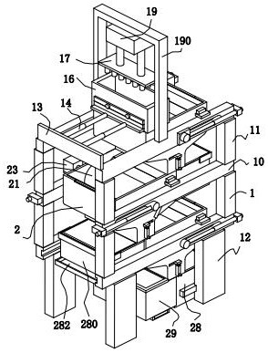
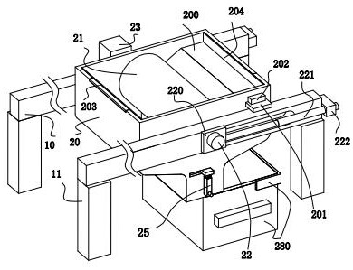
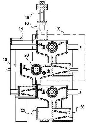
[0034] refer to figure 1 , figure 2 , image 3 and Figure 4, a steel slag magnetic separator, comprising two groups of body frames 1 and three groups of magnetic separation units 2, the body frame 1 of each group is composed of a transverse frame plate 10, a stacking bracket 11 and a ground bracket 12, and the transverse frame The plates 10 are arranged equidistantly from top to bottom, adjacent transverse frame plates 10 are connected by stackin...


PUM


Abstract

The invention relates to the technical field of steel slag magnetic separation, in particular to a steel slag magnetic separator which comprises two sets of machine body frames and three sets of magnetic separation units. The magnetic separation unit comprises a magnetic separation bin of a funnel structure, a magnetic separation roller, a mandrel, a motor, a shifting plate, a rectangular telescopic column, a lug plate, an external electric sliding block and a bearing piece used for bearing iron-containing substances. The multiple magnetic separation units are arranged from top to bottom and communicate with one another, and the beneficial effects of the magnetic separation units are that the steel slag can be subjected to multiple magnetic separation treatment, and the magnetic separation treatment of the steel slag is more sufficient, so that the selection effect of iron-containing substances in the steel slag is improved; and meanwhile, the single magnetic separation unit can also perform double magnetic separation treatment on the iron-containing substances to separate iron-free substances entrained in the iron-containing substances, so that the separation degree of the iron-containing substances in the steel slag is further improved.

Description

technical field [0001] The invention relates to the technical field of steel slag magnetic separation, in particular to a steel slag magnetic separator. Background technique [0002] Steel slag is the waste slag removed in the steelmaking process. Steel slag mainly comes from the oxides formed after the oxidation of elements contained in molten iron and scrap steel. Steel slag magnetic separation technology refers to the use of magnetism to select and recover iron-containing substances in steel slag. [0003] In the case that the magnetic separator can only perform single-stage magnetic separation treatment on steel slag, the final magnetic separation effect of steel slag is low, and if you want to achieve the purpose of multiple magnetic separation of steel slag, you need to repeatedly dump steel slag-collect steel slag- The operation steps of dumping steel slag, in this way, the labor intensity of a single batch of steel slag treatment will increase. In the case that the m...

Claims


Application Information

Patent Timeline
Patent Type & Authority Applications(China)
IPC IPC(8): B02C1/00B02C23/14B03C1/12B08B1/00B08B1/02
CPCB02C1/00B02C23/14B03C1/12B08B1/20B08B1/165Y02W30/50
Inventor 李保全张建宇彭亮赵凤彪
Owner TANGSHAN YANSHAN IRON & STEEL CO LTD
Learn More