
Flying device and method of comb and flying dyeing all-in-one machine

An all-in-one machine and comb technology, which is applied in the field of flying hair device of comb flying and dyeing all-in-one machine, can solve the problems of comb needle grinding trouble, poor effect of comb needle grinding and unevenness, etc., so as to avoid accidental injury, improve grinding and cutting precision, The effect of improving quality stability

Inactive Publication Date: 2022-05-17
宁波宇鸿正信智能科技有限公司
View PDF1 Cites 0 Cited by
  • Summary
  • Abstract
  • Description
  • Claims
  • Application Information

AI Technical Summary

Problems solved by technology

[0005] At present, it is very troublesome to polish the comb needles. Operators need to hold the comb and put it on the sanding machine to polish it. However, because the connection between the comb needle and the plastic sleeve is too tight, the distance between the ends of the two is very small. It is difficult to control the placement position of the comb with a sanding machine, resulting in a large degree of uneven damage to the plastic sleeve while grinding and cutting the comb needles. In the end, not only the grinding and cutting effect of the comb needles is poor, but the plastic sleeve is also damaged. The shape is also poor, which affects the overall quality of the comb

Method used


Image

  • Flying device and method of comb and flying dyeing all-in-one machine
  • Flying device and method of comb and flying dyeing all-in-one machine
  • Flying device and method of comb and flying dyeing all-in-one machine

Examples


Embodiment Construction

[0043] The present invention will be further described in detail below with reference to the embodiments of the accompanying drawings.

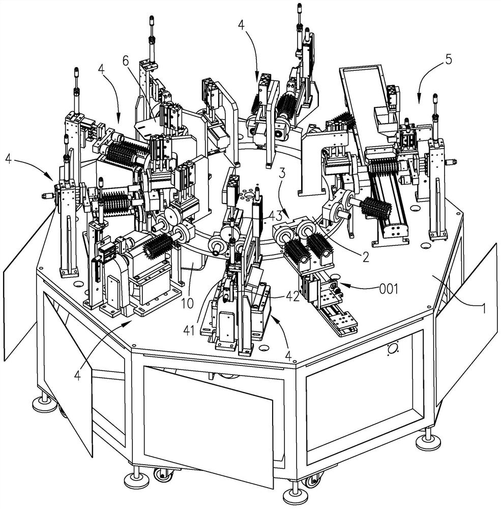
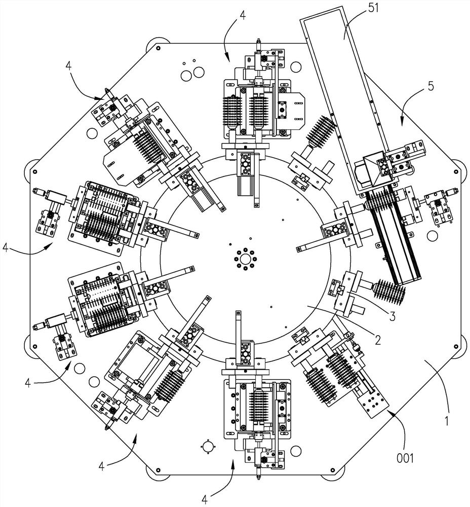
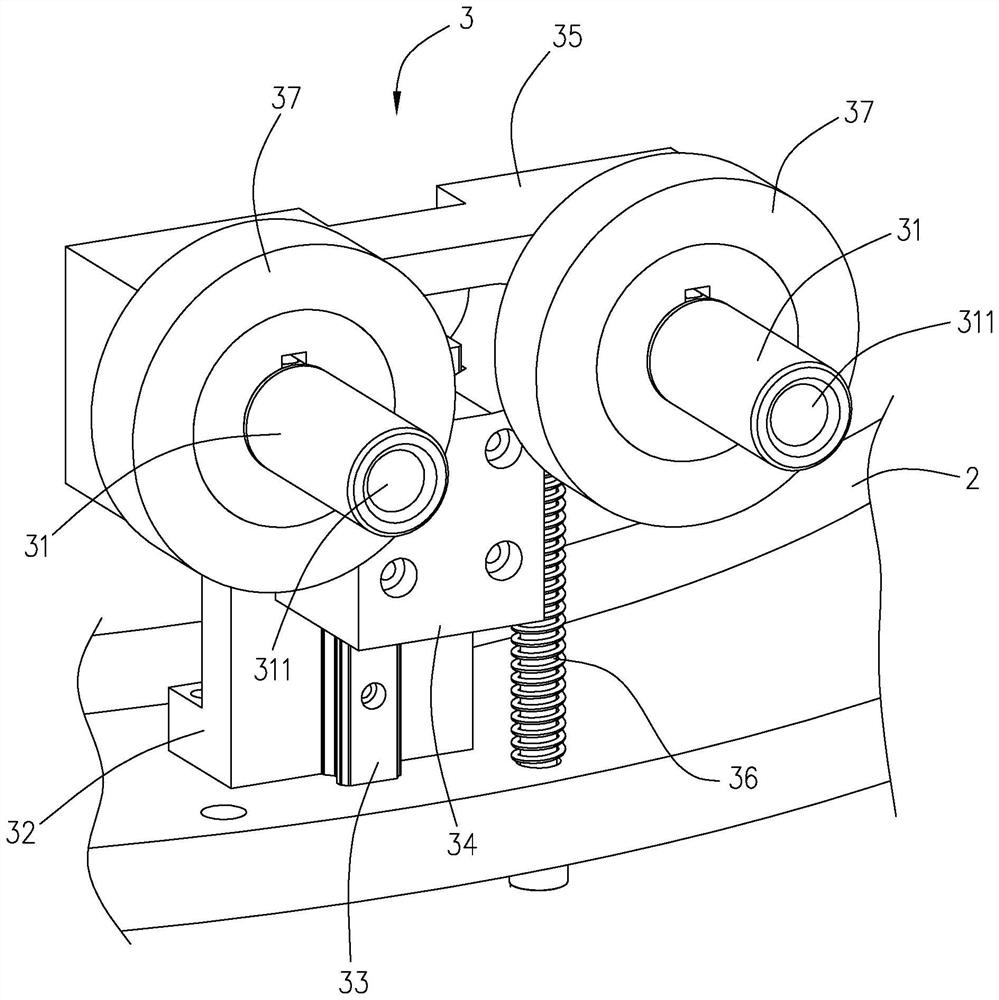
[0044] like Figures 1 to 10 As shown, the comb flying and dyeing integrated machine in this embodiment includes an assembly platform 1, a turntable 2, a first driving mechanism 10, a positioning assembly 3, a flying hair device, and a dyeing head mechanism 5, which is used for fully automatic completion of comb needle grinding. and dyeing process. This embodiment can process one or more combs at the same time. In this embodiment, four combs are processed at a time. Correspondingly, the outer circumference of the turntable 2 is provided with a feeding and unloading station and four grinding workers from front to back according to the processing sequence. position, a dye head station.

[0045] Specifically, the turntable 2 is in the shape of a disk and is rotatably provided on the assembly platform 1 , and the edge of the turntable 2 has a p...


PUM


Abstract

The invention relates to a flying device and method for a comb flying and dyeing all-in-one machine, and the device comprises a positioning assembly which comprises a clamping sleeve used for fixing a to-be-processed comb; the flying mechanism is close to the edge of the turntable, is arranged on the assembly platform and is provided with a flying cutter group which can be in contact with comb needles of the comb to grind and cut the comb in a state that the jacket moves downwards; and the flexible blocking piece is integrated with the flying mechanism and is used for allowing card wires of a comb to penetrate through to be matched with the flying knife group for sanding so as to prevent plastic sleeves on the peripheries of the card wires from being in contact with the flying knife group. When the card wires are abraded and cut, the card wires penetrate through the flexible blocking piece and make contact with the fly hair cutter set located below the flexible blocking piece for abrading and cutting, and the plastic sleeve is blocked on the flexible blocking piece and does not participate in abrading and cutting, so that only the ends of the card wires are abraded and cut, the ends of the plastic sleeve are prevented from being accidentally damaged, the abrading and cutting precision can be effectively improved, and the service life of the card wires is prolonged. Therefore, the quality stability of combs produced in the same batch is improved.

Description

technical field [0001] The invention relates to the technical field of automation equipment, in particular to a device and a method for flying hair of an integrated comb-flying-dyeing machine. Background technique [0002] Figure 10 A DP type comb is shown, the DP type comb includes a cylindrical body a and a plurality of comb needles b radially distributed on the outer peripheral surface of the body a, and a plurality of comb needles b are arranged in rows on the surface of the body a along the axis The outer circumference of the comb needle b is covered with a layer of plastic sleeve d, and the length of the plastic sleeve d is less than the length of the comb needle b, so that the root of the plastic sleeve d is arranged close to the surface of the body a, and the end is located on the comb needle b. The position of approximately the middle, that is, the end of the comb needle b is exposed outside the end of the plastic sleeve d, the interior of the body a is hollow, the...

Claims


Application Information

Patent Timeline
IPC IPC(8): B29C41/20B29C41/34B29C69/00
CPCB29C41/20B29C41/34B29C69/001
Inventor 陈奇伟相琼颖
Owner 宁波宇鸿正信智能科技有限公司
Learn More