Portable folding tent framework

A technology of tents and skeletons, applied in the field of tents, can solve problems such as difficulty in meeting capacity requirements, inconvenient carrying and use, waste of emergency rescue and disaster relief time, etc., and achieve the advantages of being easy to carry and use, light in quality and volume, and saving materials Effect

Pending Publication Date: 2022-05-17
杨均
View PDF0 Cites 0 Cited by
  • Summary
  • Abstract
  • Description
  • Claims
  • Application Information

AI Technical Summary

Problems solved by technology

A family car cannot carry a tent that can meet the capacity requirements, and the existing portable tents are difficult to meet the capacity requirements. It is often necessary to use two or three tents side by side.
If the above entertainment activities will only cause inconvenience in carrying and use, if it is applied to outdoor emergency activities such as disaster relief, it will waste a lot of rescue and disaster relief time, causing a lot of people and property losses

Method used


Image

  • Portable folding tent framework
  • Portable folding tent framework
  • Portable folding tent framework

Examples


Embodiment 1

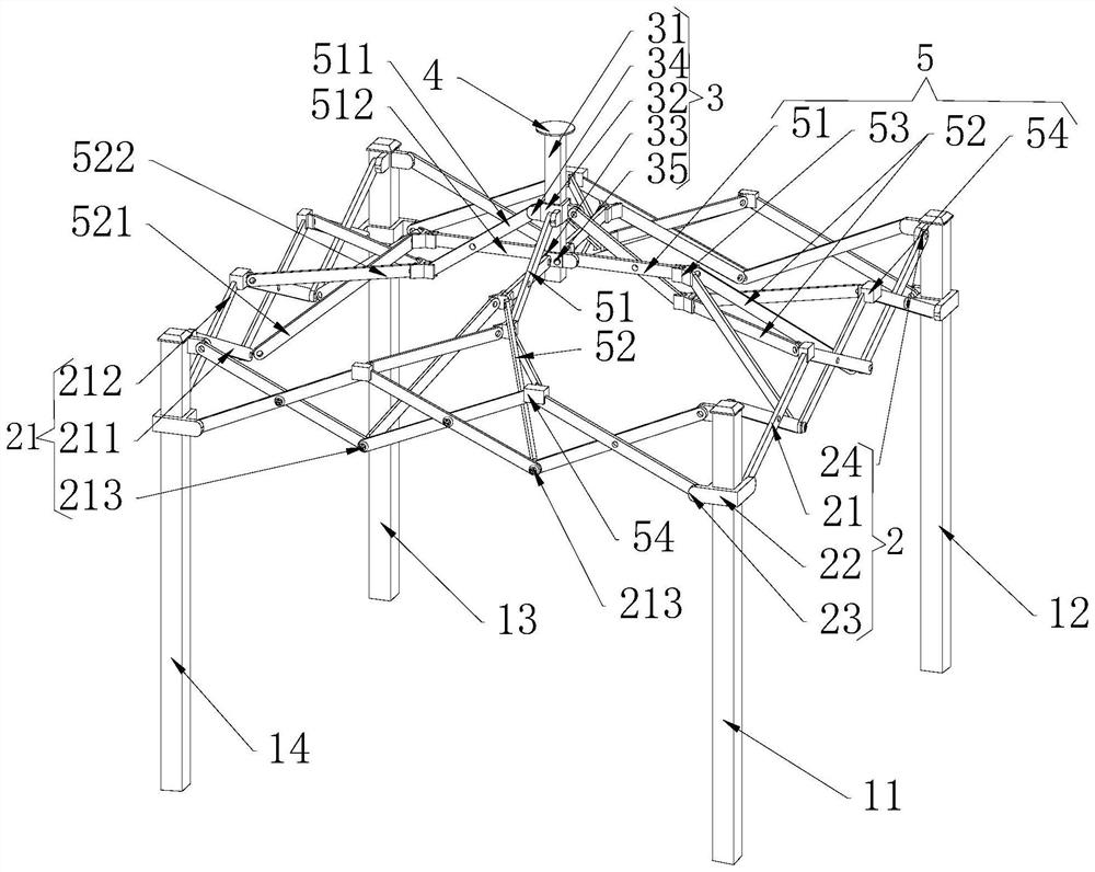
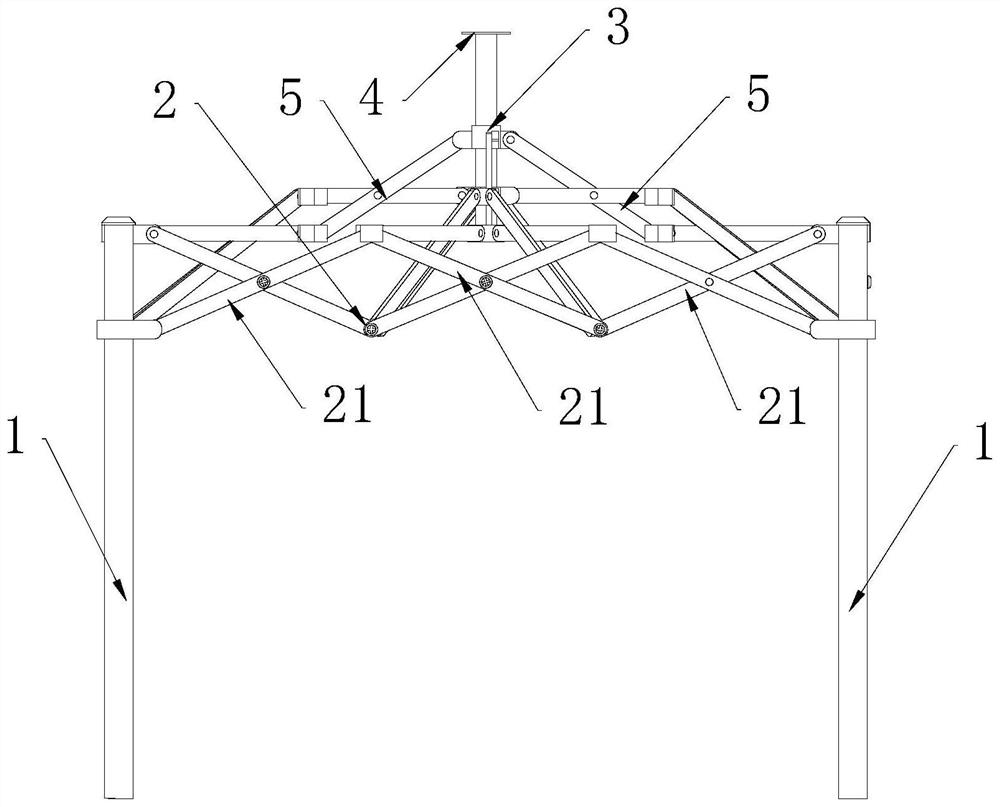
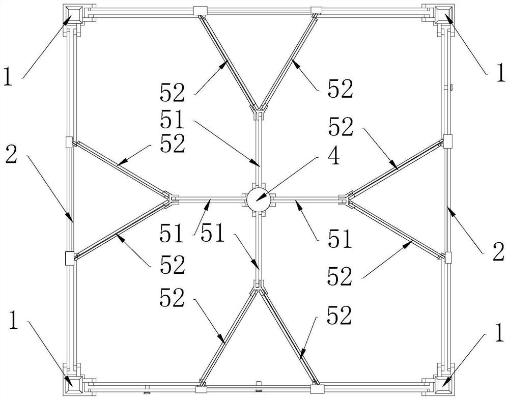
[0030] Such as figure 1 , figure 2 and image 3 Shown: a portable folding tent frame, equipped with a pole assembly 1, the pole assembly 1 is composed of pole one 11, pole two 12, pole three 13 and pole four 14, the pole one 11, Two poles 12, three poles 13 and four poles 14 are retractable square poles, or round poles. Between above-mentioned pole one 11, pole three 13 and pole four 14 and between pole one 11, pole three 13 and pole two 12, a horizontal telescopic mechanism 2 is arranged, through which the horizontal telescopic mechanism 2 can The tent is unfolded, and the pole components are used to form a stable vertical structure. Different degrees of expansion can be opened according to the needs, so that the tent can be applied to a more flexible and changeable environment.

[0031] In the middle of the plane where the first pole 11, the second pole 12, the third pole 13 and the fourth pole 14 are located, a middle support mechanism 3 is provided, and the middle supp...

Embodiment 2

[0040] Such as Figure 4 Shown: As an optimization, under the condition that other structures are the same as those in Embodiment 1, the above-mentioned horizontal telescopic mechanism 2 is provided with two sequentially connected telescopic rod groups 21, and the above-mentioned telescopic bracket assembly 5 cancels the part of the two-in-one hinge joint 53, That is to say, the telescopic bracket assembly 5 is not a two-in-one telescopic bracket, and directly supports the middle support mechanism 3 with the middle support rod group 51, so as to meet the needs of building a tent with a small area. There is a triangle between the two telescopic rod groups 21 The hinged seat 55, the two telescopic rod groups 21 and the middle support rod group 51 are all hinged together by the triangular hinged seat 55 to realize the synchronous telescopic function, and the two telescopic rod groups 21 are respectively connected to the two opposite sides of the triangular hinged seat 55. The fla...


PUM


Abstract

The invention relates to the technical field of tents, in particular to a portable folding tent framework which is provided with a vertical rod assembly (1), the vertical rod assembly (1) is composed of a first vertical rod (11), a second vertical rod (12), a third vertical rod (13) and a fourth vertical rod (14), and transverse telescopic mechanisms (2) are arranged between the first vertical rod (11) and the fourth vertical rod (14) and between the first vertical rod (11) and the second vertical rod (12); a middle supporting mechanism (3) is arranged in the middle of the plane where the first vertical rod (11), the second vertical rod (12), the third vertical rod (13) and the fourth vertical rod (14) are located, the middle supporting mechanism (3) is higher than the vertical rod assembly (1), and telescopic support assemblies (5) are arranged between the middle supporting mechanism (3) and the transverse telescopic mechanisms (2) respectively. The folding type folding tent has the advantages of being convenient to fold and carry and stable in structure, and the covering range and the space can be large enough.

Description

technical field [0001] The invention relates to the technical field of tents, in particular to a lightweight folding tent frame. Background technique [0002] With people's pursuit of rich life content, outdoor activities have become the main choice for people to relax and broaden their horizons in life, such as BBQ (barbecue), picnic and camping, etc. These projects usually require tents to resist changing weather And to deal with the wind, sand and dust in the wild. At the same time, because the more people involved, the more lively it is, the tents set up must be large enough to accommodate enough people. Family cars cannot carry tents that can meet the capacity requirements, and existing portable tents are difficult to meet the capacity requirements, and it is often necessary to use two or three tents side by side. If the above entertainment activities will only cause inconvenience in carrying and use, if they are applied to outdoor emergency activities such as disaster...

Claims


Application Information

Patent Timeline
Patent Type & Authority Applications(China)
IPC IPC(8): E04H15/50
CPCE04H15/50
Inventor 杨均
Owner 杨均
Why Eureka
Try Eureka