Drive device

A driving device and driving signal technology, which is applied in the direction of output power conversion device, static indicator, instrument, etc., can solve the problem of single-ended signal transmission speed limitation, and achieve the effect of improving signal transmission speed and increasing signal transmission speed

Pending Publication Date: 2022-05-17
AU OPTRONICS CORP
View PDF0 Cites 0 Cited by
  • Summary
  • Abstract
  • Description
  • Claims
  • Application Information

AI Technical Summary

Problems solved by technology

[0002] The signal transmission of the current light-emitting diode driver integrated circuit (LED driver IC) mostly uses single-ended signal or differential signal transmission, but the transmission speed of single-ended signal is limited. However, if you want to use differential signal transmission, you need to connect the signal line double the number

Method used


Image

  • Drive device
  • Drive device
  • Drive device

Examples


Embodiment Construction

[0047] In order to make the description of the contents of this disclosure more detailed and complete, the following is an illustrative description of the implementation pattern and specific embodiments in this case; this is not the only form of implementation or application of specific embodiments in this case. The embodiments cover the characteristics of a plurality of specific embodiments and the method steps for constructing and operating these specific embodiments and their sequence. However, other specific embodiments may also be utilized to achieve the same or equal function and step sequence.

[0048] Unless otherwise defined in this specification, the scientific and technical terms used herein have the same meaning as those understood and customary in the technical field to which the case belongs. In addition, in cases where the context does not conflict, the singular noun used in this specification covers the plural type of the noun, and the plural noun used also covers ...


PUM


Abstract

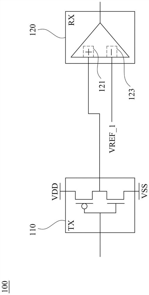
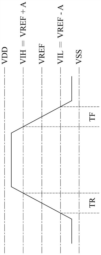
The invention discloses a driving device. The driving device comprises a first complementary metal-oxide-semiconductor circuit and a first comparator, the first complementary metal-oxide-semiconductor circuit is used for outputting a power signal or a pull-down signal according to a first input signal. The first comparator comprises a first non-inverting input end and a first inverting input end. The first non-inverted input end is coupled to the first complementary metal-oxide-semiconductor circuit and is used for receiving a power supply signal or a pull-down signal. The first reverse input end is used for receiving a first reference signal. The first comparator is used for comparing one of the power supply signal and the pull-down signal with the first reference signal to provide a first driving signal.

Description

Technical field [0001] This case relates to display devices and, in particular, to a drive device applied to light-emitting diode displays. Background [0002] The signal transmission of the current light-emitting diode drive integrated circuit (LED driver IC) mostly uses single-ended signals or differential signal transmission, but the transmission speed of single-ended signals is limited, however, if you want to use differential signal transmission, you need to double the number of signal lines. Contents of the Invention [0003] The content of the Invention is intended to provide a simplified summary of the contents of this disclosure so that the reader has a basic understanding of the contents of this disclosure. The contents of this invention are not a complete overview of the contents of this disclosure, and they are not intended to identify important / key elements of the embodiments of this case or to define the scope of this case. [0004] A technical sample of the con...

Claims


Application Information

Patent Timeline
Patent Type & Authority Applications(China)
IPC IPC(8): H02M1/08G09G3/32
CPCH02M1/08G09G3/32G09G3/2096G09G2370/10G09G2370/14H03K19/018521H03K17/6872
Inventor 耿启育杜明鸿陈雅芳杨智翔
Owner AU OPTRONICS CORP
Why Eureka
Try Eureka