Servo drive type floating mechanism

A floating mechanism and servo-driven technology, which is applied in the direction of grinding drive, grinding machine parts, workpiece feed movement control, etc., can solve problems such as unstable quality, low efficiency, and different shapes

Pending Publication Date: 2022-05-20
许又升
View PDF0 Cites 0 Cited by
  • Summary
  • Abstract
  • Description
  • Claims
  • Application Information

AI Technical Summary

Problems solved by technology

However, due to the different shapes of various workpieces, the difficulty of automation is quite high, and it is quite dependent on manual hand-held pneumatic or electric tools for processing
This processing method is inefficient and unstable in quality

Method used


Image

  • Servo drive type floating mechanism
  • Servo drive type floating mechanism
  • Servo drive type floating mechanism

Examples


no. 1 example

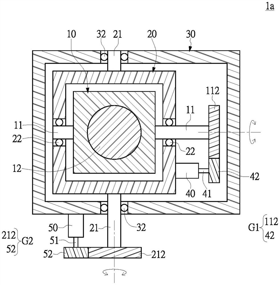
[0028] Such as Figure 1 to Figure 3 As shown, the present invention provides a servo-driven floating mechanism (servo type compliant mechanism) 1a, which includes a holding seat 10, a grinding tool 12, an attitude sensor 18, a displacement sensor 19, an inner frame 20, an outer The frame 30 , a first servo motor 40 and a second servo motor 50 .

[0029] The grinding tool 12 is held in the holding seat 10 , the first pivot 11 is fixedly connected to the holding seat 10 , and the first pivot 11 is perpendicular to the axial direction of the grinding tool 12 . Abrasive tool 12 may be pneumatic or electric. The rotational speed of the electric grinding tool is adjustable.

[0030] In this embodiment, the holding seat 10 and the grinding tool 12 are disposed in the inner frame 20 , and the first pivot 11 of the grinding tool 12 is movably disposed in the inner frame 20 . In other words, the grinding tool 12 can rotate within the inner frame 20 along the first pivot 11 to adjust...

no. 2 example

[0045] Such as Figure 6 Shown is a schematic cross-sectional view of the servo-driven floating mechanism 1b according to the second embodiment of the present invention. The difference between this embodiment and the above-mentioned embodiments is that this embodiment is a direct drive type, that is to say, this embodiment can omit the above-mentioned gear set. In other words, the motor of the present invention can drive the grinding tool 12 in different ways. Specifically, the first servo motor 40 has a first driving member 43 connected to the grinding tool 12 . The first servo motor 40 in this embodiment may be a linear motor, or a rotary motor coupled with a linear transmission mechanism. For example, the driving part of the linear motor can be a ball screw shaft, the ball screw shaft is directly connected to the grinding tool 12, and the ball screw shaft can generate linear motion, which can drive the grinding tool 12 along the first pivot 11 to produce relative to the i...


PUM


Abstract

A servo drive type floating mechanism comprises a holding seat, a grinding tool, a posture sensor, a displacement sensor, an inner frame and a first servo motor. The grinding tool is clamped in the holding seat, and the grinding tool is provided with a first pivot and a grinding tool body. The first pivot is perpendicular to the axis direction of the grinding tool. The posture sensor is used for sensing the posture of the grinding tool and sending out a posture signal, and the posture signal is calculated to obtain a torque compensation value aiming at the influence of gravity. The displacement sensor is used for sensing the displacement amount of the grinding tool along the first pivot. The grinding tool is arranged in the inner frame, and a first pivot of the grinding tool is movably arranged in the inner frame. The first servo motor is arranged in the inner frame and drives the grinding tool to rotate along the first pivot according to the torque compensation value and the displacement, so that torsion output by the grinding tool is not affected by gravity in various postures.

Description

technical field [0001] The invention relates to a servo-driven floating mechanism, which belongs to the technical field of mechanical processing, in particular to a grinding and polishing device which is applied to remove burrs of workpieces and can automatically compensate. Background technique [0002] After the preliminary manufacturing of the workpiece is completed, it needs to be processed to remove burrs, surface grinding, polishing and other post-processing processes. However, due to the different shapes of various workpieces, the difficulty of automation is quite high, and it is quite dependent on manual hand-held pneumatic or electric tools for processing. This processing method is inefficient and unstable in quality. [0003] With the development of industrial automation, for the sake of production efficiency, it has gradually developed into automatic removal of workpiece burrs. The key is how to automatically adjust the pressing force between the grinding tool a...

Claims


Application Information

Patent Timeline
Patent Type & Authority Applications(China)
IPC IPC(8): B24B9/00B24B55/00B24B41/00
CPCB24B9/00B24B55/00B24B41/007B24B41/04B24B47/12B24B27/0084B24B49/12B24B49/10B24B47/22
Inventor 许又升
Owner 许又升
Why Eureka
Try Eureka