
Crane

A crane and boom technology, which is applied to cranes, clockwork mechanisms, hoisting devices, etc., can solve the problems of low operation efficiency, twisted steel strands, large tower cranes affecting construction efficiency, etc., to reduce construction costs, The effect of improving construction efficiency

Pending Publication Date: 2022-05-20
威胜利工程有限公司
View PDF0 Cites 0 Cited by
  • Summary
  • Abstract
  • Description
  • Claims
  • Application Information

AI Technical Summary

Problems solved by technology

[0003] 1. After arranging the steel strands into bundles on the ground, use a large tower crane to lift one end to the top of the assembled cylinder, so that the occupation of the large tower crane will affect the overall construction efficiency
[0004] 2. Install a hoist on the top surface of the assembly cylinder, lift the individual steel strands in sequence and then organize them into bundles. In this way, a total of 200 to 300 steel strands need to be lifted, and the operation efficiency is low and it is not easy to bundle the steel strands. Prone to twisting of steel strands

Method used


Image

  • Crane
  • Crane
  • Crane

Examples


Embodiment 1

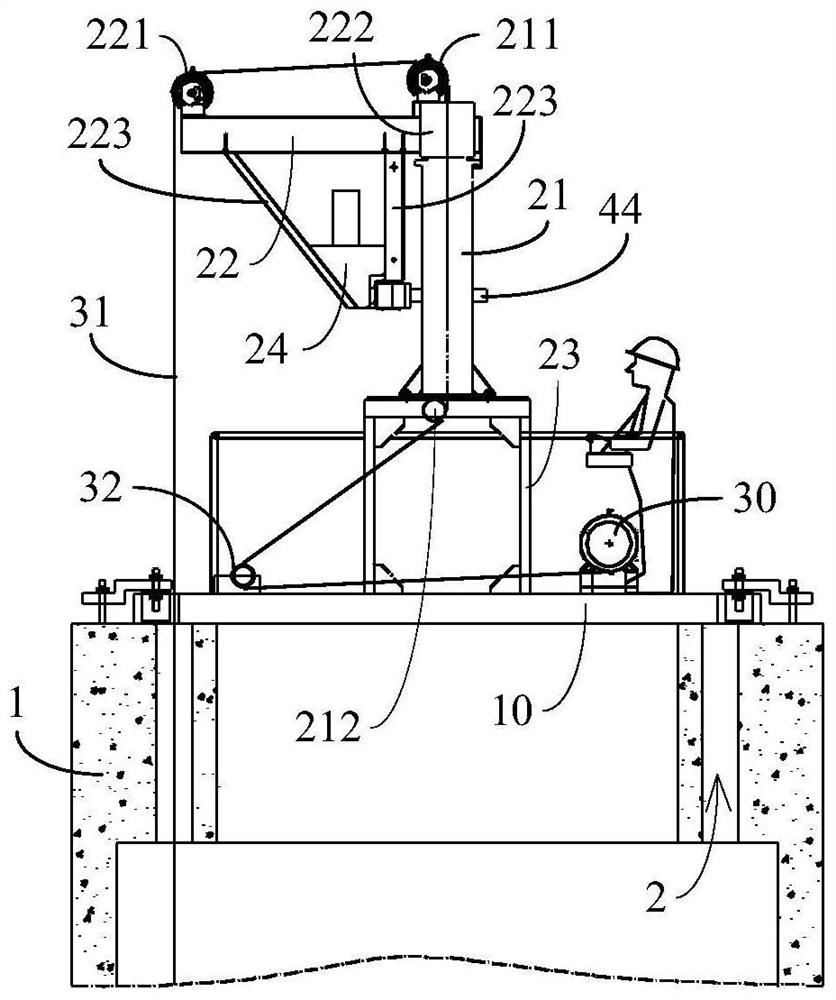
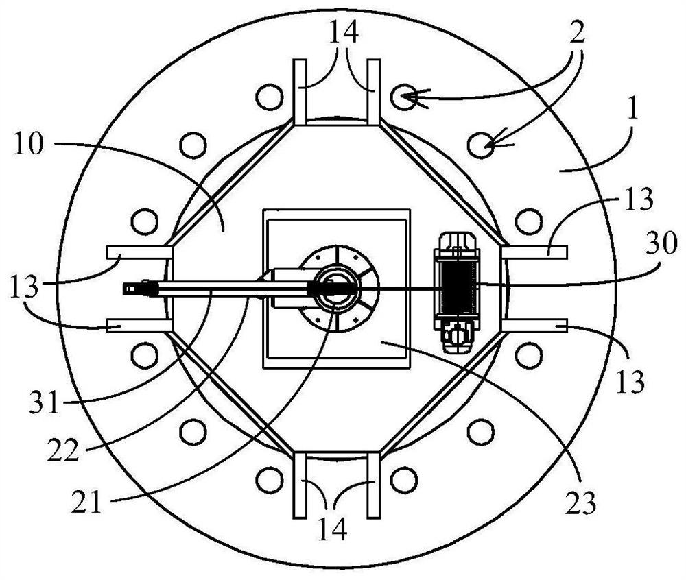
[0018] A crane, the base 10 has a column 21 vertically arranged, the upper end of the column 21 is connected with a boom 22 extending in a cantilever shape, the boom 22 rotates around the axis of the column 21, a winch 30 is arranged on the base 10, and is wound on the winch 30 After the traction rope 31 on the bobbin is drawn out, it is arranged to be suspended from bottom to top along the column 21, along the suspension arm 22 from inside to outside at the suspension end of the suspension arm 22.

[0019] as attached Figure 1-3 As shown, the cable hole 2 is usually arranged around the core of the concrete tower body 1 . When in use, the base 10 is installed on the top of the concrete tower body 1, so that the axis of the column 21 coincides with the axis of the tower body 1, and the extension length of the boom 22 is the same as that reserved on the tower body 1. The cable hole 2 is consistent with the distance from the shaft center of the tower body 1, so that the tractio...

Embodiment 2

[0027] The difference between this embodiment and Embodiment 1 is that the base 10 is composed of several base bodies that are detachably connected, which is convenient for the transportation of the crane. Hoist 30, support 23 and reversing wheel 32 are fixedly installed on the same base. Specific as attached Figure 4-6 As shown, the base 10 includes a strip-shaped middle seat 11 as a whole, side seats 12 are symmetrically arranged on both sides of the middle seat 11, and a winch 30, a bracket 23 and a reversing wheel 32 are fixedly installed on the middle seat. 11 above, shipped as attached Figure 5 As shown, the middle seat body 11 and the two side seat bodies 12 are separated, and if the transportation height is limited, the column 21 and the bracket 23 can be further separated. This example is attached Figure 6 As shown, two trapezoidal side seats 12 are symmetrically arranged on both sides of the middle seat 11, and the base 10 is generally in the shape of a regular...


PUM


Abstract

The invention belongs to the technical field of construction machinery, and particularly relates to a crane which is characterized in that a vertical column is vertically arranged on a base, the upper end of the vertical column is connected with a suspension arm extending in a cantilever shape, the suspension arm rotates around the axis of the vertical column, and a winch is arranged on the base; and the suspension ends of the suspension arms are suspended downwards from bottom to top along the stand columns and from inside to outside along the suspension arms. The base of the crane can be stably installed on the top of the tower drum and provide a reliable installation platform for the suspension arm, the suspension arm can rotate around the stand column to the position above the cable penetrating holes, traction operation of the whole bundle of prestressed tendons is safely and reliably achieved, construction efficiency is remarkably improved, and construction cost is reduced.

Description

technical field [0001] The invention belongs to the technical field of construction machinery, in particular to a crane. Background technique [0002] The concrete cylinder of the wind power tower is usually prefabricated in sections and hoisted at the construction site. After the hoisting is completed, prestressed tendons are arranged circumferentially around the cylinder to apply prestress to the assembled tower to improve the bending resistance of the assembled cylinder. The prestressed tendons need to be pulled from the bottom of the tower to the top of the assembled cylinder by a hoist. Each bundle of prestressed tendons is composed of multiple steel strands, with a length of up to 100 meters and a weight of two tons. The installation space on the top of the assembled cylinder is limited, and it is impossible to reliably fix the high-power hoist to pull the whole bundle of prestressed tendons. At present, the following two methods are usually used to realize the tractio...

Claims


Application Information

Patent Timeline
Patent Type & Authority Applications(China)
IPC IPC(8): B66C23/02B66C23/18B66C23/62B66C23/84B66D1/12B66D3/08
CPCB66C23/022B66C23/18B66C23/025B66C23/62B66C23/84B66D1/12B66D3/08Y02E10/72
Inventor 杨明李厚宝张雷
Owner 威胜利工程有限公司
Learn More