
Separation traction device
A traction device and adjustment device technology, applied in packaging, transportation and packaging, paper/cardboard containers, etc., can solve the problems of inconspicuous indentation, damage to paper, machine failure, etc., to improve operation stability, improve versatility, The effect of a high degree of automation
- Summary
- Abstract
- Description
- Claims
- Application Information
AI Technical Summary
Problems solved by technology
Method used
Image

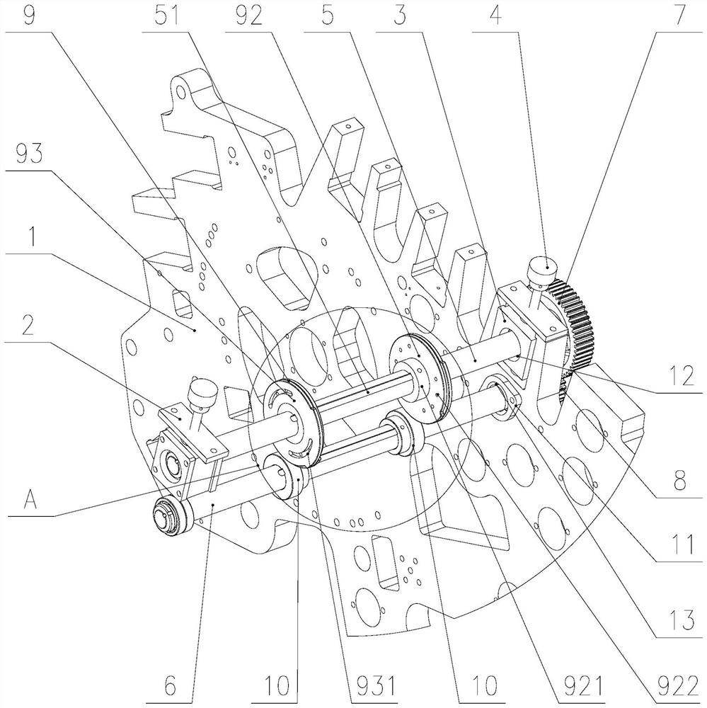
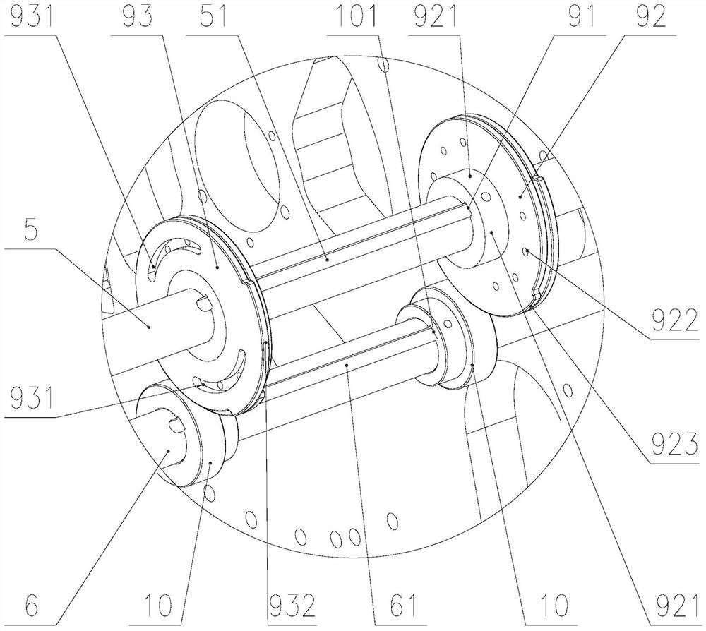
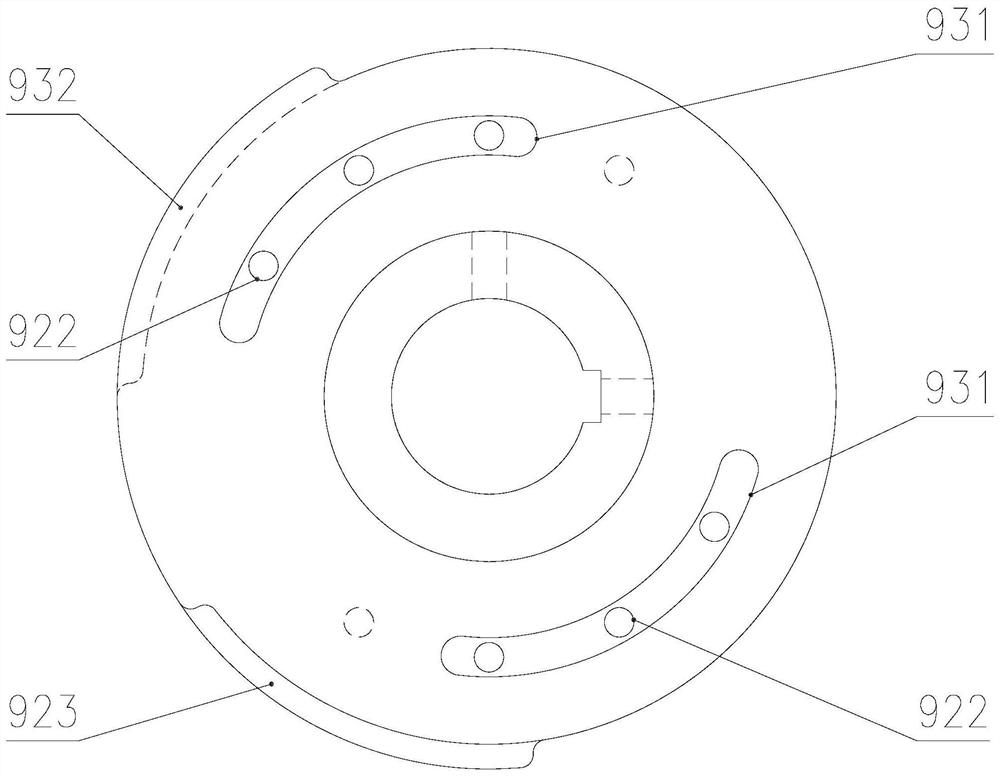
Examples
Embodiment Construction
[0022] The preferred embodiments of the present invention are described in detail below with reference to the accompanying drawings, so that the advantages and features of the present invention can be more easily understood by those skilled in the art, and the protection scope of the present invention can be more clearly defined.
[0023] like figure 1 The shown tensioning and pulling device includes a wall plate 1, two fixed plates 2 symmetrically connected to the wall plates 1 on both sides, two sliding blocks 3, two sliding block adjusting devices 4, and pulling material. The pressing roller shaft 5, the pulling material pulling lower shaft 6 arranged in parallel under the pulling material pulling pressing roller shaft 5, the pulling material pulling gear 7 and the pulling lower gear 8 arranged on the outer side of the wall panel 1, two groups of pulling pressure Wheel assembly 9 and two pulling pulleys 10 for pulling material.
[0024] The sliders 3 are respectively arran...
PUM
 Abstract
Description
Claims
Application Information