Installation method of condenser
An installation method and condenser technology, which are applied in the processing of building materials, auxiliary equipment of nuclear power plants, and reduction of greenhouse gases, can solve the problems of increasing other operations, shortening the construction period, and time-consuming alignment operations, so as to prevent product damage, The effect of reducing the amount of waste materials and reducing the workload
- Summary
- Abstract
- Description
- Claims
- Application Information
AI Technical Summary
Problems solved by technology
Method used
Image
Examples
no. 1 Embodiment
[0058] The first embodiment ( Figure 1 ~ Figure 3 )
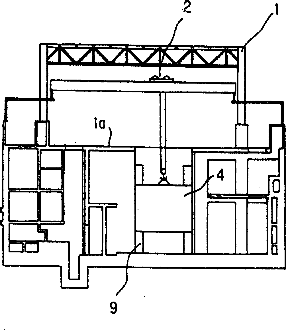
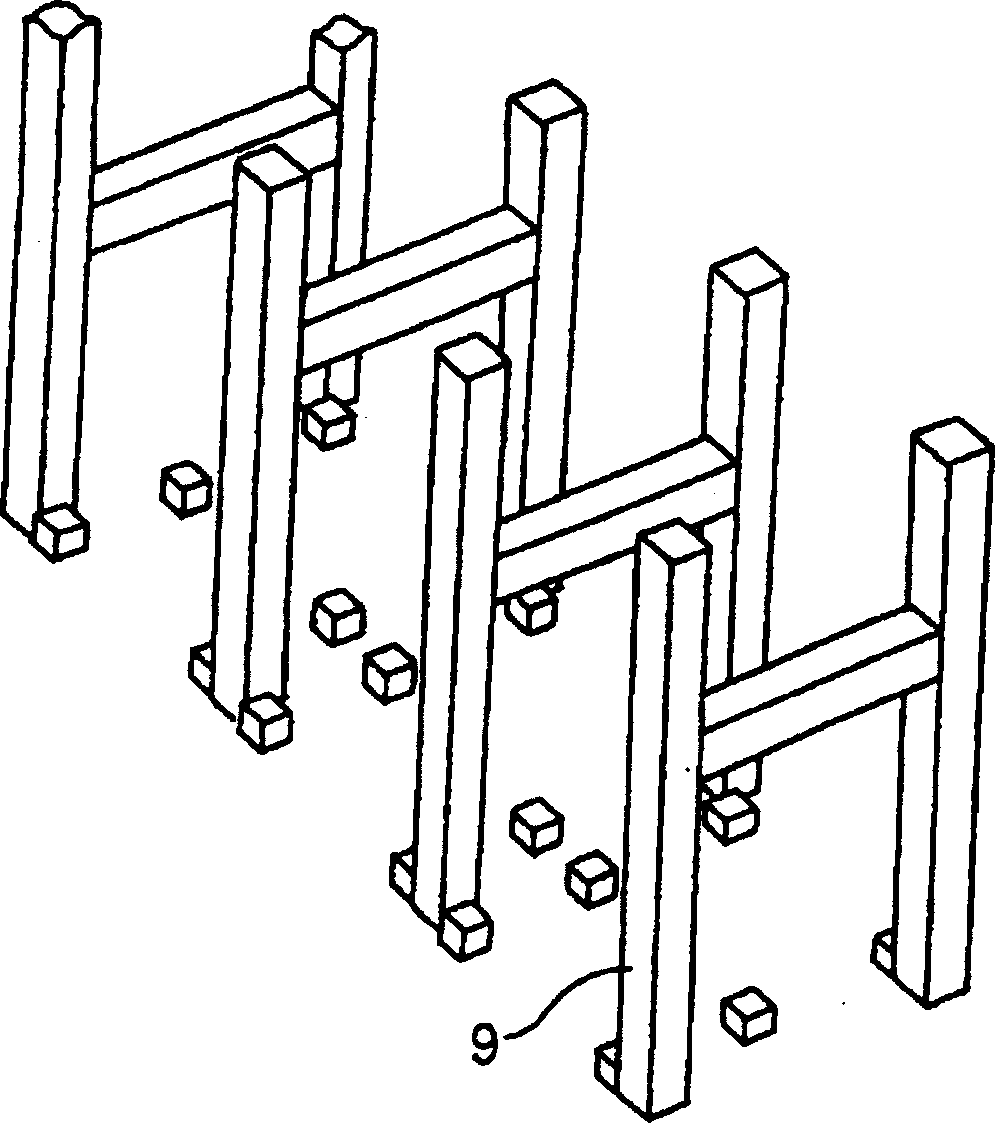
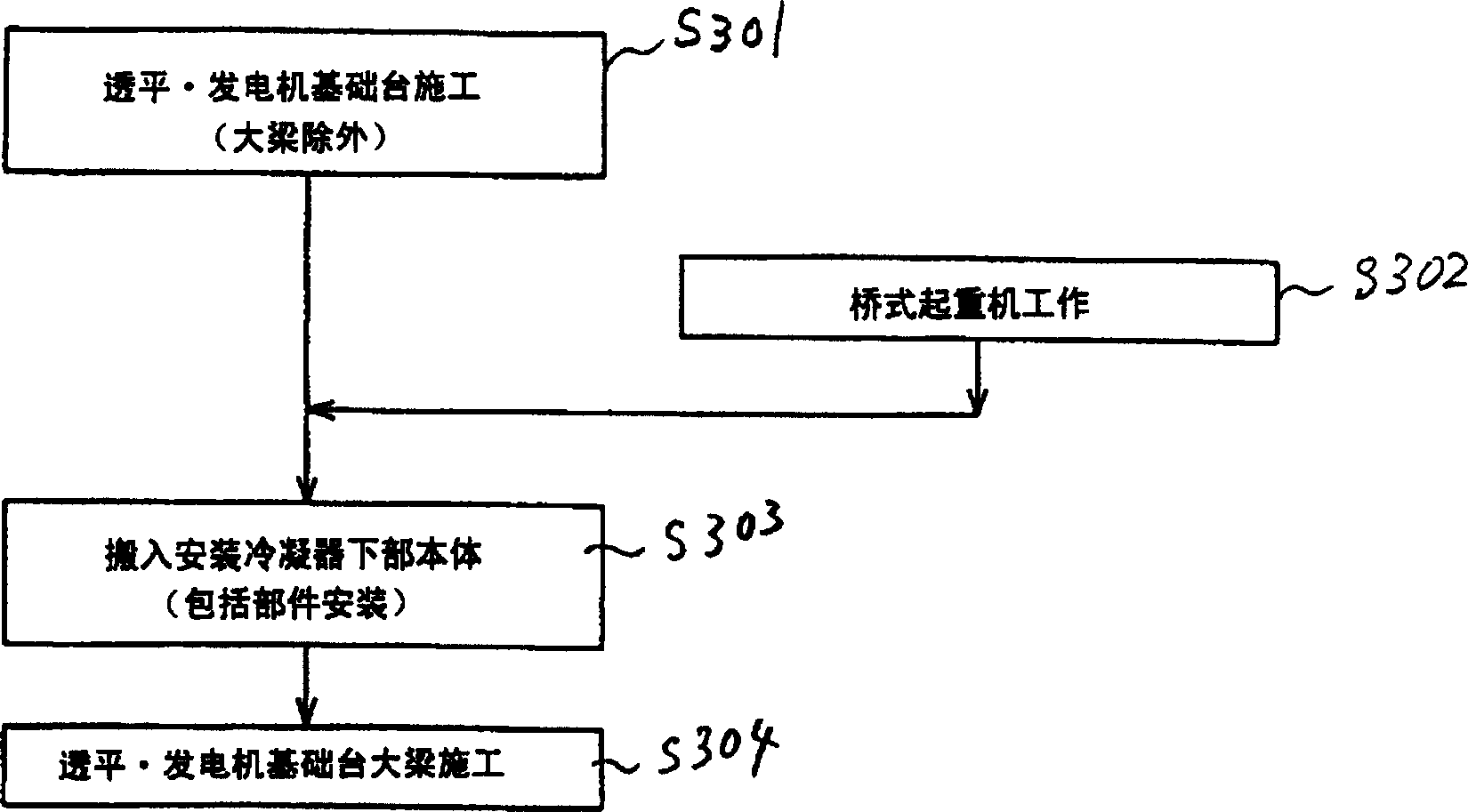
[0059] figure 1 It is an overall view for explaining the installation method of the condenser according to the first embodiment of the present invention. figure 2 will be figure 1 The illustrated turbogenerator base 9 is an enlarged perspective view. image 3 It is a figure which shows the installation procedure of the condenser of this embodiment.
[0060] Such as figure 1 As shown, in the present embodiment, the turbine building 1 is constructed by the steel bar main body construction method, and the outer wall maintenance is carried out at the same time from the initial stage of construction of the turbine building 1 to the construction of the roof. That is, it is a so-called all-weather construction method in which the bridge crane 2 starts working from the initial stage.
[0061] In this turbine building 1, a foundation platform 9 for a turbine generator is constructed, Figure 7 , Figure 8 The girder 12 ...
no. 2 Embodiment
[0066] The second embodiment ( Figure 4 )
[0067] Figure 4 It is an overall perspective view illustrating the installation method of the condenser according to the second embodiment of the present invention.
[0068] In the present embodiment, similarly to the first embodiment, the turbine building 1 is constructed by the steel main body construction method, and the external wall maintenance is performed simultaneously from the initial stage of construction of the turbine building 1 to the construction of the roof. That is, it is a building of the so-called all-weather construction method in which the bridge crane 2 works from the initial stage.
[0069] In the present embodiment, too, in the turbine building 1, the foundation platform 9 of the turbine generator is constructed first, and the construction of the girder 12 has not yet been carried out. In this state, in the present embodiment, the condenser lower body 4 that is equipped with cooling pipes and is divided in...
no. 3 Embodiment
[0073] The third embodiment ( Figure 5 )
[0074] Figure 5 It is an overall view illustrating the installation method of the condenser according to the third embodiment of the present invention.
[0075] Such as Figure 5 As shown, the present embodiment is also the same as the first embodiment, the turbine building 1 is constructed by the steel main body construction method, and the outer wall maintenance is carried out at the same time from the initial stage of construction of the turbine building 1 to the construction of the roof. That is, it is a so-called all-weather construction method in which the bridge crane 2 starts working from the initial stage. In this turbine building 1, the foundation platform 9 of the turbine generator has been constructed earlier, and the construction of the girder 12 has not yet been carried out.
[0076] In this embodiment, in this state, the lower body 4 of the condenser that is not equipped with cooling pipes is directly hoisted in w...
PUM
 Abstract
Description
Claims
Application Information
 - R&D
- Intellectual Property
- Life Sciences
- Materials
- Tech Scout
- Unparalleled Data Quality
- Higher Quality Content
- 60% Fewer Hallucinations
Browse by: Latest US Patents, China's latest patents, Technical Efficacy Thesaurus, Application Domain, Technology Topic, Popular Technical Reports.
© 2025 PatSnap. All rights reserved.Legal|Privacy policy|Modern Slavery Act Transparency Statement|Sitemap|About US| Contact US: help@patsnap.com


