
Box-type filter core air tightness detection device

A technology of air tightness detection and filter core, which is applied in the liquid/vacuum degree of liquid tightness measurement, by detecting the appearance of fluid at the leak point, and improving air quality, etc., can solve the waste of working time, inconvenience, influence Use effect, etc.

Pending Publication Date: 2022-05-20
宿迁菲优特空气净化设备有限公司
View PDF0 Cites 0 Cited by
  • Summary
  • Abstract
  • Description
  • Claims
  • Application Information

AI Technical Summary

Problems solved by technology

[0002] During the processing of the filter core, it will be partially welded according to the actual situation, and then assembled as a whole. However, for later air tightness testing, due to the continuity of the process flow, it may be found that the parts with poor airtightness are the previous workpieces during the search, so it is necessary to remove the previous workpieces and continue to repair the leakage. Assembling, this form will affect the overall work efficiency and waste working time in the actual working process. At the same time, when it is inspected as a whole, it will cause partial leakage due to the volume of the filter, which will affect the subsequent use effect.
[0003] In summary, there are obviously inconveniences and defects in the actual use of the existing technology, so it is necessary to improve

Method used


Image

  • Box-type filter core air tightness detection device
  • Box-type filter core air tightness detection device
  • Box-type filter core air tightness detection device

Examples


Embodiment Construction

[0021] In order to make the objectives, technical solutions and advantages of the present invention clearer, the present invention will be described in further detail below in conjunction with the accompanying drawings and embodiments. It should be understood that the specific embodiments described here are only used to explain the present invention and are not intended to limit the invention.

[0022] It should be noted that, in the description of the present invention, terms such as "upper", "lower", "left", "right", "inner", "outer" and other indicated directions or positional relationships are based on the terms shown in the accompanying drawings. The direction or positional relationship shown is only for convenience of description, and does not indicate or imply that the device or element must have a specific orientation, be constructed and operated in a specific orientation, and thus should not be construed as limiting the present invention.

[0023] In addition, it shou...


PUM


Abstract

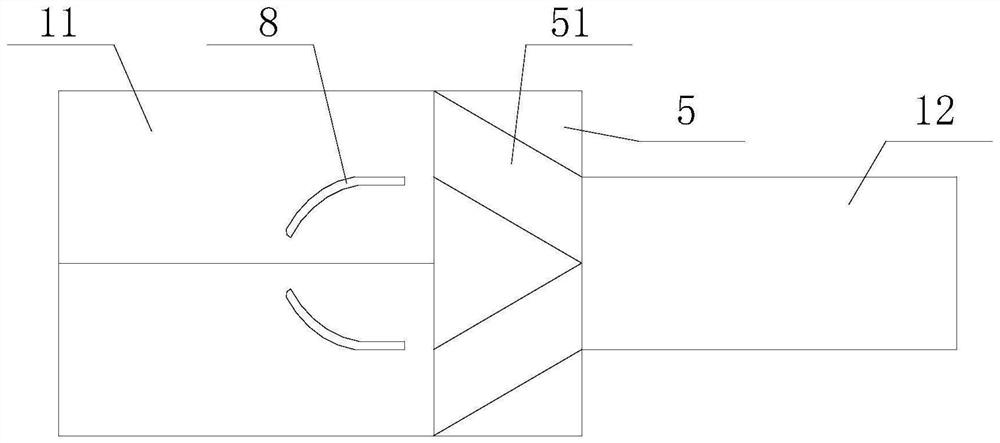
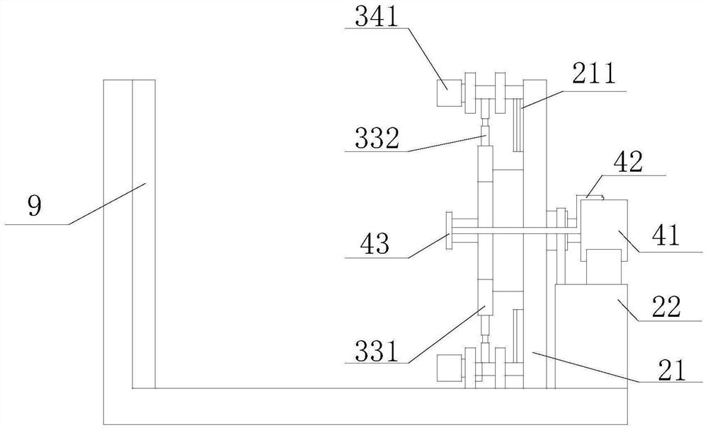
The invention is suitable for the technical field of detection, and provides a box-type filter core air tightness detection device, which comprises a conveying device, a limiting device and a detection structure, and is characterized in that the conveying device comprises a branch conveying belt and a total conveying belt, and the branch conveying belt is provided with a direction changing mechanism; the limiting device comprises a vertical plate, a driving part and a clamping part, the clamping part comprises a rotating plate, a fixing plate, a connecting rod and a clamping plate, the driving part is connected with the rotating plate through a rotating shaft, the fixing plate is fixedly connected with the rotating plate, the two ends of the connecting rod are connected with the clamping plate and the fixing plate respectively, a guide block is arranged on the vertical plate, and the clamping plate is slidably connected with the guide block; the detection structure comprises a telescopic piece and an air guide pipe, the telescopic piece is fixedly connected with the vertical plate and penetrates through the rotating plate, the air outlet device is connected with the air guide pipe, and a groove for containing the air guide pipe is formed in the telescopic piece. Therefore, the air tightness detection of the core body can be effectively realized, the automatic detection and conveying of the core body are realized, and the overall working efficiency is improved.

Description

technical field [0001] The invention relates to the technical field of airtightness detection, in particular to an airtightness detection device for a box-type filter core. Background technique [0002] During the processing of the filter core, it will be partially welded according to the actual situation, and then assembled as a whole. However, for later air tightness testing, due to the continuity of the process flow, it may be found that the parts with poor airtightness are the previous workpieces during the search, so it is necessary to remove the previous workpieces and continue to repair the leakage. Assembling, this form will affect the overall work efficiency and waste working time during the actual work process. At the same time, when the overall inspection is performed, it will cause partial leakage due to the volume of the filter, which will affect the subsequent use effect. [0003] In summary, there are obviously inconveniences and defects in the actual use of ...

Claims


Application Information

Patent Timeline
IPC IPC(8): G01M3/06
CPCG01M3/06Y02A50/20Y02E30/30
Inventor 徐发庚
Owner 宿迁菲优特空气净化设备有限公司
Learn More