Thermal protection type piezoresistor with controlled device
A varistor and controlled device technology, applied in varistors, overvoltage protection resistors, resistors, etc., can solve problems such as the inability to actively disconnect the circuit and the inability of the thermal fuse to sense the varistor in time. Avoid the effect of fire
- Summary
- Abstract
- Description
- Claims
- Application Information
AI Technical Summary
Problems solved by technology
Method used
Image

Examples
Embodiment 1
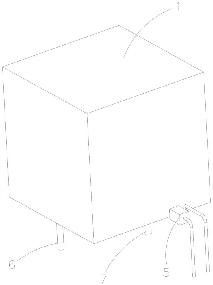
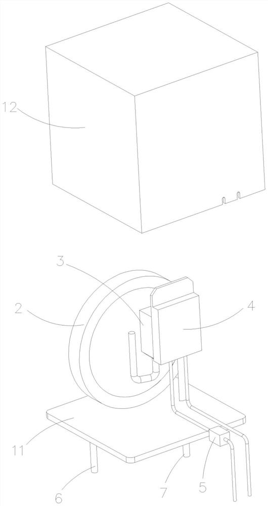
[0036] see figure 1 and figure 2 , the present invention provides a thermally protected varistor with a controlled device, the thermally protected varistor with a controlled device includes a housing 1, a varistor 2, a thermal fuse 3, a heating device 4, a control device 5, the first lead-out electrode 6 and the second lead-out electrode 7, one of the pins of the thermal fuse 3 is connected in series with one of the pins of the varistor 2, and the other pin of the varistor 2 It is connected to the first lead-out electrode 6 , the other pin of the thermal fuse 3 is connected to the second lead-out electrode 7 , and the first lead-out electrode 6 and the second lead-out electrode 7 extend out of the housing 1 . Wherein, the heating device 4 is attached to the thermal fuse 3 , the heating device 4 is electrically connected to the control device 5 , and the control device 5 controls the heating device 4 to heat up so that the thermal fuse 3 is blown.
[0037] More specifically,...
Embodiment 2
[0043] see Figure 5 , the structure of a thermally protected varistor with a controlled device in this embodiment is basically the same as that of Embodiment 1, the difference is that the control device 5 is installed in the housing 12 and cannot communicate through optical communication or For other direct communication control, in this embodiment, the control device 5 is turned on by installing an APP program built into the chip and by external wireless control or wired electrical control. Embodiment 1 and Embodiment 2 are both single-line control methods, that is, the external detection device is used to detect the abnormal overcurrent or abnormal temperature of the piezoresistor, and then the APP program is used to remotely control the opening of the heating device.
Embodiment 3
[0045] see Figure 6 In this embodiment, a thermally protected varistor with a controlled device has basically the same structure as that of Embodiment 1, the difference is that the control device 5 is a two-wire control, and the control device 5 includes a temperature rise control module ( not shown in the figure) and a piezoresistor detection module (not shown in the figure), the temperature rise control module controls the heating device 4 to achieve rapid temperature rise, and the piezoresistor detection module detects the current or temperature of the piezoresistor 2, The temperature rise control module controls the opening of the temperature rise device 4 according to the detection result of the piezoresistor detection module. Compared with the single-line control, the two-line control can enable the control 5 to obtain data on the abnormal current or temperature of the varistor 2 in a shorter time, open the heating device 4 faster and disconnect the thermal fuse 3, and ...
PUM
 Abstract
Description
Claims
Application Information
 - R&D
- Intellectual Property
- Life Sciences
- Materials
- Tech Scout
- Unparalleled Data Quality
- Higher Quality Content
- 60% Fewer Hallucinations
Browse by: Latest US Patents, China's latest patents, Technical Efficacy Thesaurus, Application Domain, Technology Topic, Popular Technical Reports.
© 2025 PatSnap. All rights reserved.Legal|Privacy policy|Modern Slavery Act Transparency Statement|Sitemap|About US| Contact US: help@patsnap.com