
Integrated reaction precipitation separation tank
A precipitation separation and precipitation tank technology, applied in the field of precipitation tanks, can solve the problems affecting the normal use of precipitation and separation tanks, large volume of stirring and cleaning components, lack of cleaning effect, etc., and achieves good applicability, small size, and improved secondary pollution. Effect
- Summary
- Abstract
- Description
- Claims
- Application Information
AI Technical Summary
Problems solved by technology
Method used
Image

Examples
Embodiment
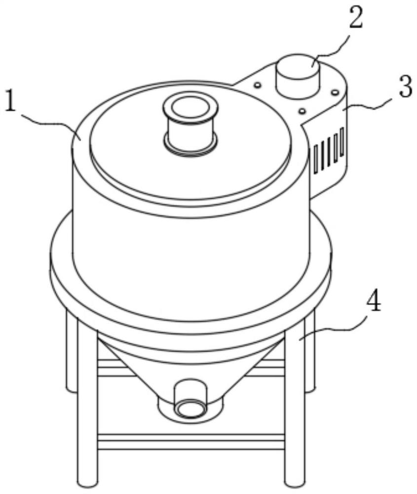
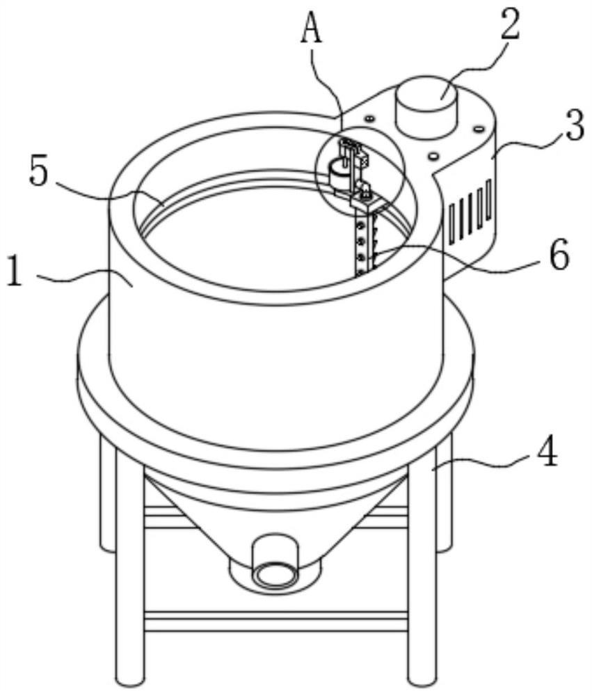
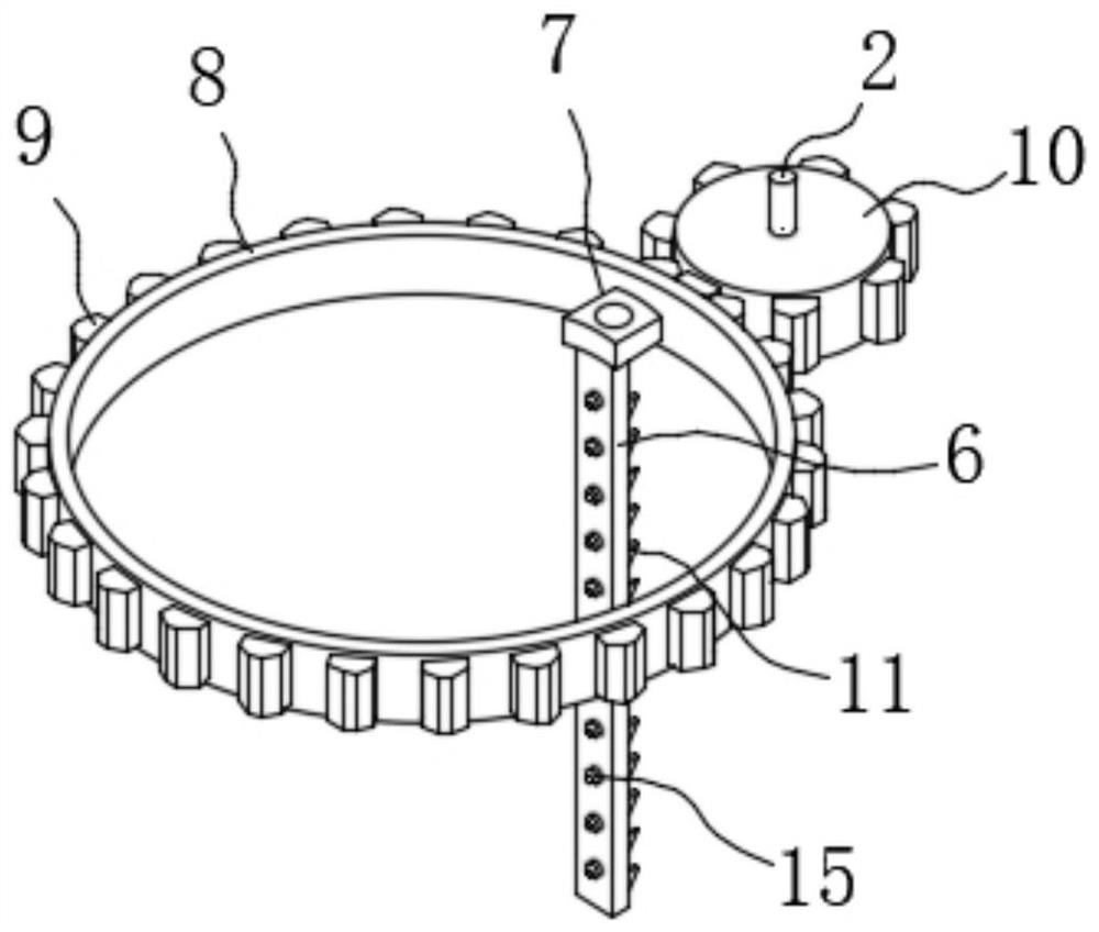
[0024] like Figure 1-Figure 6 The shown integrated reaction sedimentation separation tank includes a sedimentation tank body 1, a chassis 3 is arranged on the back of the sedimentation tank body 1, an inner notch 5 is opened on the inner wall of the sedimentation tank body 1, and a servo motor 2 is installed on the upper surface of the chassis 3. , the output shaft of the servo motor 2 is fixedly connected with a gear 10, a transmission ring body 8 is arranged in the inner slot 5, the outer wall of the transmission ring body 8 is meshed with the gear 10 through the teeth 9, and the inner wall of the transmission ring body 8 is fixedly connected with a A vertical plate 6 is fixedly connected to the lower surface of the installation block 7 , a plurality of scrapers 11 are arranged on the back of the vertical plate 6 , and a plurality of baffles 13 are fixedly connected to the back of the vertical plate 6 .
[0025] During use, when it is necessary to clean the sedimentation se...
PUM
 Abstract
Description
Claims
Application Information