Computer fan blade machining device

A processing device and computer technology, which can be applied to spray devices, devices for applying liquid to surfaces, and cleaning methods using tools, etc., can solve the problems of fan blade paint waste, fan blade surface corrosion, fan blade surface paint damage, etc. Achieving the effect of increasing cleaning effect and avoiding waste

Pending Publication Date: 2022-05-24
HARBIN FINANCE UNIV
View PDF0 Cites 0 Cited by
  • Summary
  • Abstract
  • Description
  • Claims
  • Application Information

AI Technical Summary

Problems solved by technology

[0003] In the process of painting the fan blades of traditional large computer fans, the painting equipment is used to spray paint on one side of the fan blades one by one, which leads to low painting efficiency of the fan blades, and if the fan blades are directly removed after painting, it may be damaged due to the wet paint. Cause damage to the paint on the surface of the fan blades, affecting the integrity of the paint on the surface of the fan blades, thus increasing the possibility of rust on the surface of the fan blades
[0004] Since the number of computer fan blades is different, the distance between the fan blades is also different. Traditional spraying equipment cannot perform intermittent spraying on fans with different numbers of fan blades. The spraying equipment is still working when the equipment is installed, resulting in waste of paint during the spraying process of the fan blades, resulting in an increase in the cost of fan blade spraying

Method used


Image

  • Computer fan blade machining device
  • Computer fan blade machining device
  • Computer fan blade machining device

Examples


Embodiment Construction

[0036] Embodiments of the present invention are described in detail below with reference to the accompanying drawings, but the present invention can be implemented in many different ways as defined and covered by the claims.

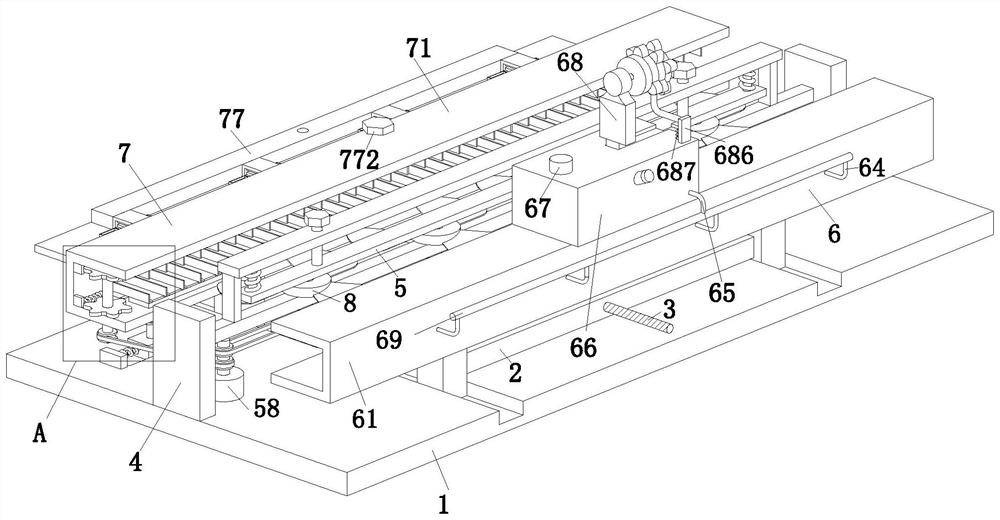
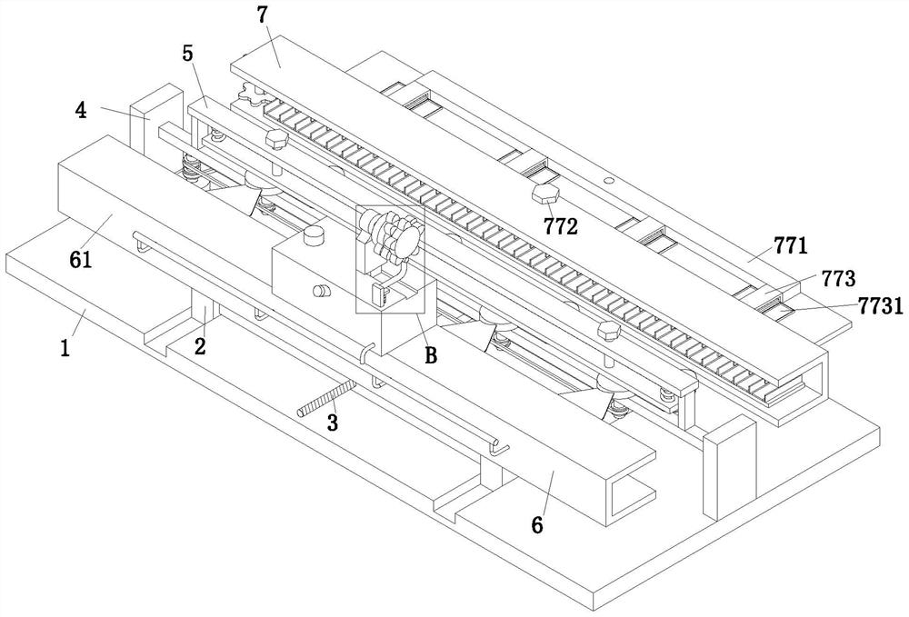
[0037] see figure 1 as well as figure 2 , a computer fan blade processing device, including a processing table 1, an H-shaped moving plate 2, a two-way screw 3, a clamping vertical plate 4, a clamping mechanism 5, a spraying mechanism 6 and a drying mechanism 7, the processing table 1. A clamping vertical plate 4 is installed in the middle of the left and right sides. A clamping mechanism 5 is installed between the two clamping vertical plates 4 and the upper end surface of the processing table 1. The upper end of the processing table 1 is symmetrically sliding in front and back. 2. A fixed protrusion is arranged in the middle of the upper end face of the processing table 1, and a bidirectional screw 3 is installed on the fixed protrusion from front to...


PUM


Abstract

The invention relates to the technical field of computer fans, in particular to a computer fan blade machining device which comprises a machining table, an I-shaped moving plate, a bidirectional lead screw, a clamping vertical plate, a clamping mechanism, a spraying mechanism and a drying mechanism. The multiple rotating shafts can clamp and limit the multiple fans through mutual cooperation of the pressing blocks and the bearing plates, so that the multiple fans can be sprayed through mutual cooperation of the multiple rotating shafts and the spraying mechanism; according to the number of fan blades, an electric sliding block is started to move a proper rotating disc to the position over an adjusting connecting block through mutual cooperation of an adjusting block and an adjusting motor, and then the adjusting motor rotates to drive an opening and closing plate to move up and down intermittently; therefore, when the pressure pump pumps paint into the spray head, intermittent start-stop adjustment can be conducted on the spray head through cooperation of the pressure pump and the opening and closing plate, the situation that the spray head still works when the gap between the two fan blades passes through the spray head is prevented, and paint waste is avoided.

Description

technical field [0001] The present invention relates to the technical field of computer fans, and in particular to a computer fan blade processing device. Background technique [0002] Because the CPU of small computers does not generate much heat, and in order to save the production cost of computers, the fan blades of small computers are often molded by plastic injection. , aluminum and other metal products have good thermal conductivity to dissipate heat inside the large computer CPU. The large computer fan blades are usually fixed on the rotating disk by welding. After the large computer fan blades are welded, the fan blades usually need to be welded. Spray paint treatment to prevent the rust of the fan blades caused by moisture and impurities in the air. [0003] In the traditional large-scale computer fan blade painting process, the single side of the fan blade is sprayed one by one through the spraying equipment, which leads to the lower painting efficiency of the fa...

Claims


Application Information

Patent Timeline
IPC IPC(8): B05B13/02B05B16/20B05D3/04B08B1/00B08B1/02B08B13/00
CPCB05B13/0292B05B13/0228B05B16/20B05D3/0413B08B13/00B08B1/143B08B1/20Y02P70/10
Inventor 南洋
Owner HARBIN FINANCE UNIV
Why Eureka
Try Eureka