Temporary installation tool for prefabricated concrete wallboard
A technology for installing tools and concrete wall panels, which is applied in the processing of building materials, construction, building construction, etc., can solve the problems of inconvenient disassembly and assembly, labor-intensive, etc., to avoid safety accidents, save personnel, and increase the number of turnover times Effect
- Summary
- Abstract
- Description
- Claims
- Application Information
AI Technical Summary
Problems solved by technology
Method used
Image
Examples
Embodiment 1
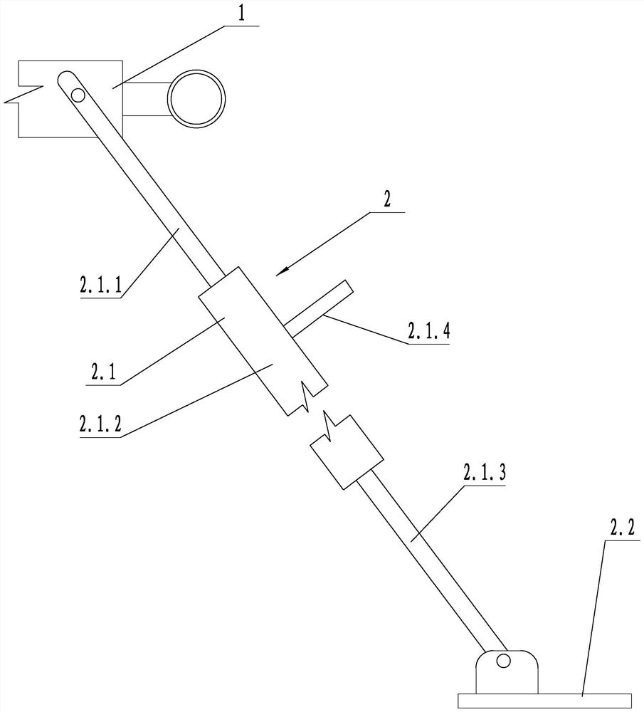
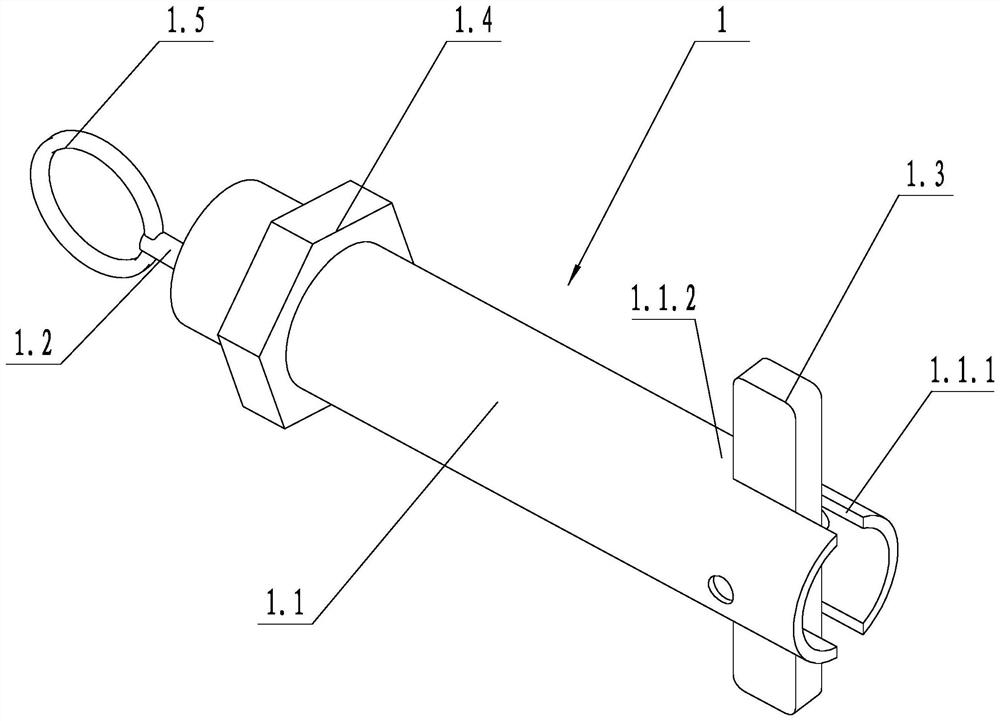
[0026] like figure 1 As shown, a temporary installation tool for prefabricated concrete wall panels includes a temporary fixture 1 and a diagonal brace assembly 2, such as figure 2 , image 3 and Figure 4 As shown, the temporary fixture 1 includes a support tube 1.1, an operating rod 1.2, a locking strip 1.3 and an adjusting nut 1.4, the width of the locking strip 1.3 is less than or equal to the outer diameter of the support tube 1.1, and the middle position of the locking strip 1.3 and the support tube 1.1 Hinged, one end of the operating rod 1.2 is set inside the support tube 1.1 and is hinged with the locking strip 1.3, the other end of the operating rod 1.2 protrudes out of the support tube 1.1, and the hinge point between the locking strip 1.3 and the support tube 1.1 is the first hinge The hinge point between the locking strip 1.3 and the operating rod 1.2 is the second hinge point, the first hinge point and the second hinge point are eccentrically arranged, and the...
Embodiment 2
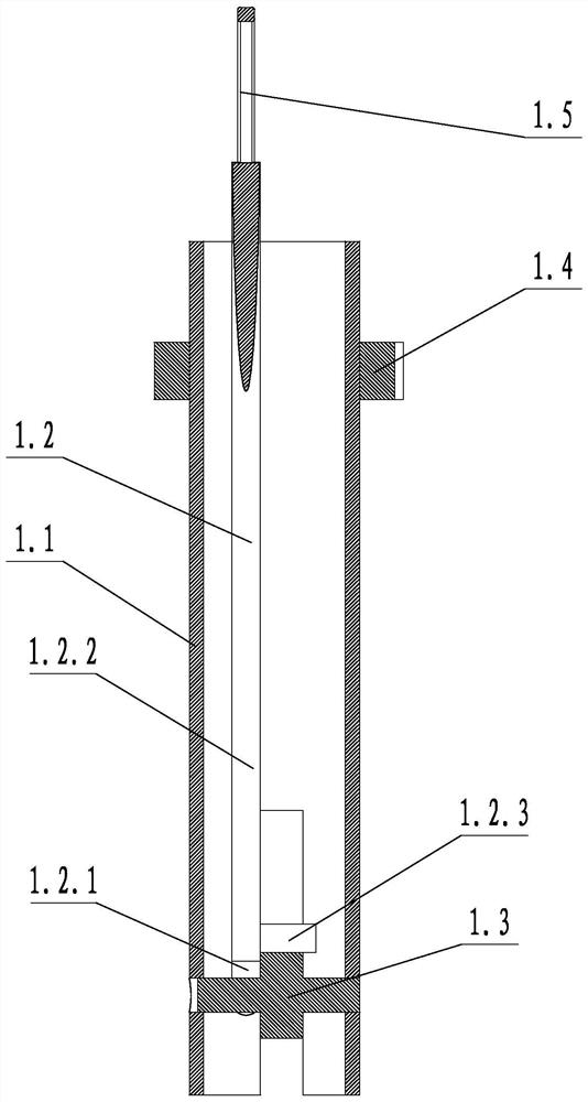
[0030] like image 3 As shown, the operating rod 1.2 includes a front rod 1.2.1 and a rear rod 1.2.2, the front rod 1.2.1 and the rear rod 1.2.2 are rotatably connected along the axis of the operating rod 1.2, and the front rod 1.2.1 is connected with the lock The tightening bar 1.3 is hinged, and the side wall of the rear rod 1.2.2 is provided with a limiting bar 1.2.3. When the locking bar 1.3 is perpendicular to the support tube 1.1, the limiting bar 1.2.3 is in contact with the side wall of the locking bar 1.3. A torsion spring is arranged between the front rod 1.2.1 and the rear rod 1.2.2, and the torsion spring keeps the length direction of the limit rod 1.2.3 and the length direction of the locking strip 1.3 in a vertical state. With the structure, after the worker releases the rear rod 1.2.2, the limit rod 1.2.3 can be returned to the position, and the locking strip 1.3 can be limited. A pull ring 1.5 is provided on one end of the rear section rod 1.2.2 away from the ...
PUM
 Abstract
Description
Claims
Application Information
 - R&D
- Intellectual Property
- Life Sciences
- Materials
- Tech Scout
- Unparalleled Data Quality
- Higher Quality Content
- 60% Fewer Hallucinations
Browse by: Latest US Patents, China's latest patents, Technical Efficacy Thesaurus, Application Domain, Technology Topic, Popular Technical Reports.
© 2025 PatSnap. All rights reserved.Legal|Privacy policy|Modern Slavery Act Transparency Statement|Sitemap|About US| Contact US: help@patsnap.com


