Graphic image data information extraction device
A technology for data information and extraction devices, which is applied in image communication, television, machine sets/supports, etc., can solve problems such as increasing device costs, inability to adjust the distance between the lens and the product, and image blurring, and achieve the effect of reducing costs
- Summary
- Abstract
- Description
- Claims
- Application Information
AI Technical Summary
Problems solved by technology
Method used
Image

Examples
Embodiment 1
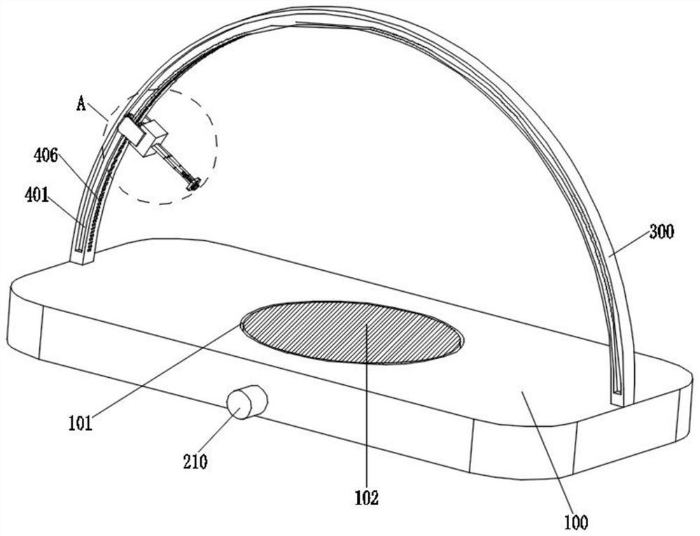
[0034] refer to Figure 1-6 A graphic image data information extraction device as shown includes a bottom plate 100, a groove 101 is formed on the upper surface of the bottom plate 100, a placing plate 102 is arranged inside the groove 101, and a rotating assembly 200 is arranged on the lower surface of the placing plate 102, An arc-shaped bracket 300 is fixedly installed on the upper surface of the bottom plate 100 , a mounting block 301 is arranged on the inner side of the arc-shaped bracket 300 , a moving assembly 400 is arranged between the installation block 301 and the arc-shaped bracket 300 , and a lens 302 is arranged on the outer side of the mounting block 301 , a telescopic assembly 500 is arranged between the mounting block 301 and the lens 302 .
[0035] Based on the above structure, by arranging the rotating assembly 200, the placing plate 102 can be rotated, and the product placed on the upper surface of the placing plate 102 can be rotated for the purpose of rot...
Embodiment 2
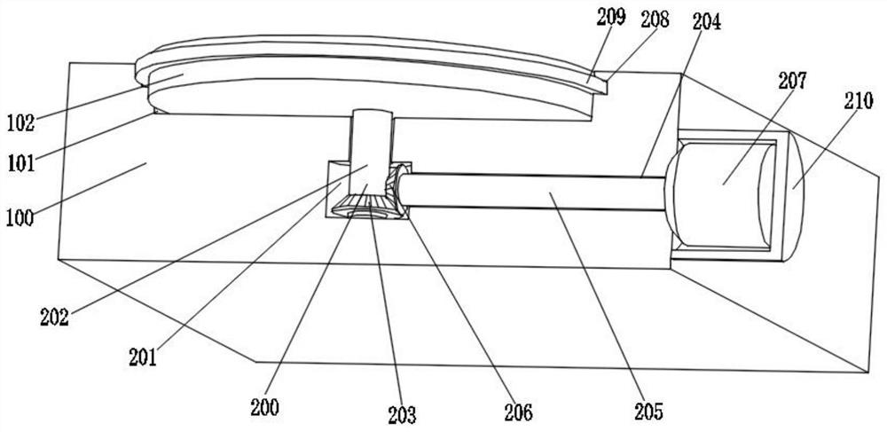
[0037] combine figure 1 and image 3 As shown, based on the above-mentioned Embodiment 1, the rotating assembly 200 includes a movable slot 201 opened inside the bottom plate 100 , a first rotating rod 202 is fixedly installed on the lower surface of the placing plate 102 , and the end of the first rotating rod 202 penetrates through The bottom wall of the groove 101 extends into the movable groove 201, and the end of the first rotating rod 202 is rotatably connected to the bottom wall of the movable groove 201. The outer surface of the first rotating rod 202 is sleeved with a bevel gear A203, and the movable groove 201 The right side wall is provided with a communication groove 204, and the communication groove 204 extends to the outside of the bottom plate 100, a second rotating rod 205 is arranged inside the communication groove 204, and the left end of the second rotating rod 205 extends into the movable groove 201. A bevel gear B206 is fixedly installed on the left ends ...
Embodiment 3
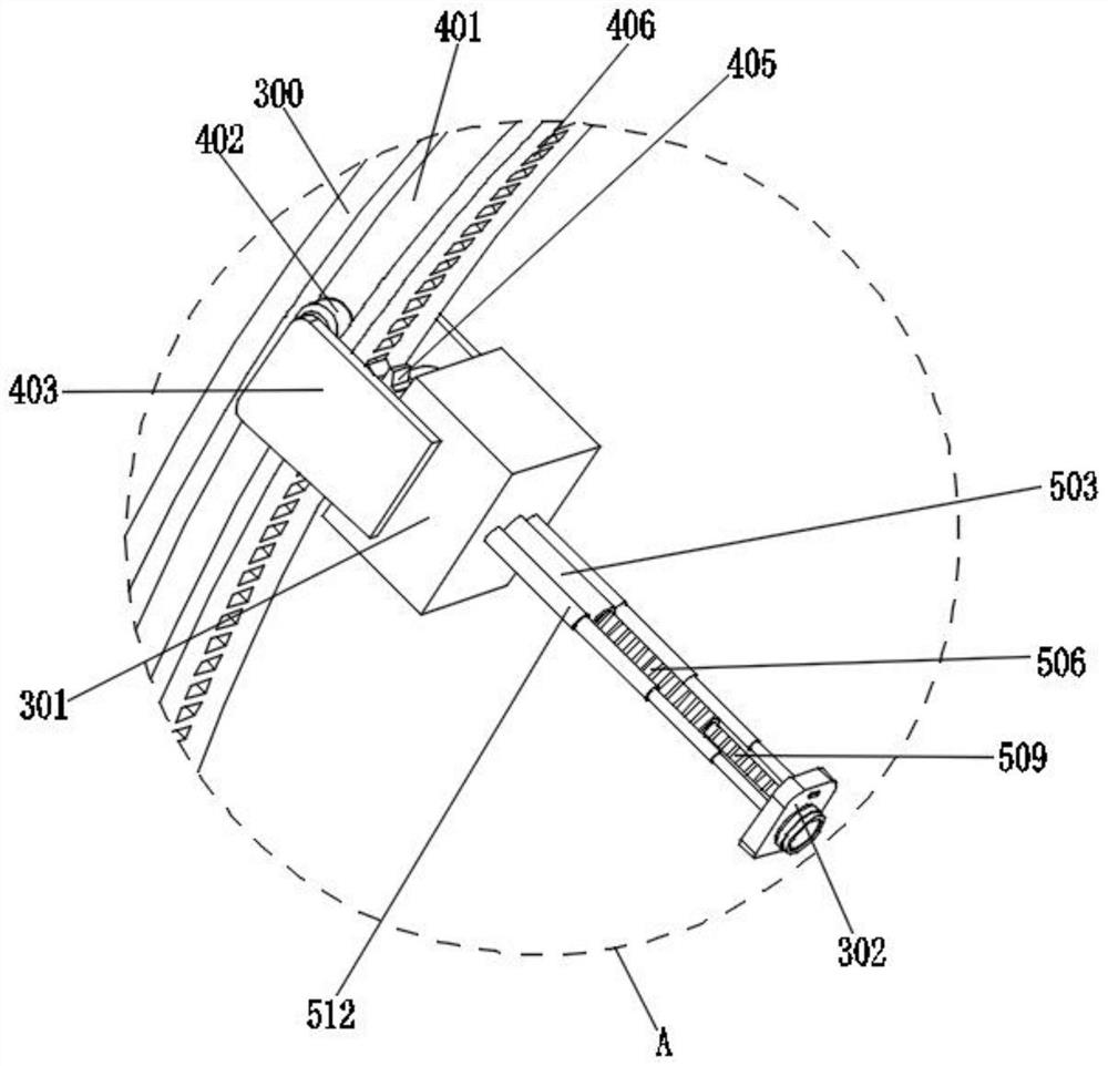
[0039] combine figure 1 , figure 2 , Figure 5 and Image 6 As shown, based on the above-mentioned Embodiment 1 or 2, the moving assembly 400 includes two sets of limit slots 401 opened on the outer surfaces of both sides of the arc-shaped bracket 300, and two sets of moving wheels 402 are provided inside the two sets of limit slots 401. The outer surfaces of the four groups of moving wheels 402 corresponding to each other are provided with side plates 403 , and the outer surfaces of the four groups of moving wheels 402 are rotatably connected with the inner sides of the two groups of side plates 403 , and the inner sides of the two groups of side plates 403 are all rotatably connected. It is fixedly connected with the outer surfaces of the two sides of the mounting block 301 , the inner side of the right side plate 403 is fixedly installed with the second motor 404 , the end of the output shaft of the second motor 404 is fixedly installed with the drive gear 405 , and the ...
PUM
 Abstract
Description
Claims
Application Information
 - R&D
- Intellectual Property
- Life Sciences
- Materials
- Tech Scout
- Unparalleled Data Quality
- Higher Quality Content
- 60% Fewer Hallucinations
Browse by: Latest US Patents, China's latest patents, Technical Efficacy Thesaurus, Application Domain, Technology Topic, Popular Technical Reports.
© 2025 PatSnap. All rights reserved.Legal|Privacy policy|Modern Slavery Act Transparency Statement|Sitemap|About US| Contact US: help@patsnap.com