
Bridge monitoring method, system and device based on micro vibration amplification technology

A micro-vibration and motion amplification technology, used in measuring devices, pattern recognition in signals, and measurement of ultrasonic/sonic/infrasonic waves. Effect

Inactive Publication Date: 2022-05-24
HUNAN UNIV
View PDF4 Cites 5 Cited by
  • Summary
  • Abstract
  • Description
  • Claims
  • Application Information

AI Technical Summary

Problems solved by technology

The existing bridge health detection schemes are mainly divided into two types. One is to directly install various sensors on the bridge and analyze the data collected by the sensors to detect abnormalities in the bridge structure. However, the cost of installing sensors is high, and Complicated installation, fewer measuring points
Another solution is to take video of the bridge through the camera, and monitor the health of the bridge by identifying the vibration of the bridge through the video. However, since the vibration displacement amplitude of the bridge with a small and medium span is very small, it is difficult to directly measure the bridge with a small and medium span based on the video captured by the camera. monitor the health status of

Method used


Image

  • Bridge monitoring method, system and device based on micro vibration amplification technology
  • Bridge monitoring method, system and device based on micro vibration amplification technology
  • Bridge monitoring method, system and device based on micro vibration amplification technology

Examples


Embodiment Construction

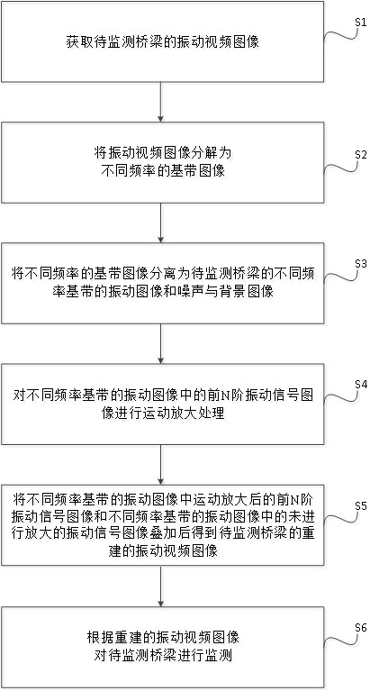
[0043] The core of the present invention is to provide a bridge monitoring method, system and device based on the micro vibration amplification technology, which realizes the monitoring of bridges with very small vibration amplitudes such as bridges with medium and small spans, and does not require additional sensors and reduces costs. .

[0044] In order to make the purposes, technical solutions and advantages of the embodiments of the present invention clearer, the technical solutions in the embodiments of the present invention will be clearly and completely described below with reference to the accompanying drawings in the embodiments of the present invention. Obviously, the described embodiments These are some embodiments of the present invention, but not all embodiments. Based on the embodiments of the present invention, all other embodiments obtained by those of ordinary skill in the art without creative efforts shall fall within the protection scope of the present inven...


PUM


Abstract

The invention discloses a bridge monitoring method, system and device based on a tiny vibration amplification technology, and the method comprises the steps: decomposing a vibration video image of a to-be-monitored bridge into baseband images with different frequencies, and separating out the vibration images of the to-be-monitored bridge from the baseband images with different frequencies; the method comprises the following steps: respectively carrying out motion amplification on first N orders of vibration signal images in vibration images of different frequency base bands of a to-be-monitored bridge, so that tiny vibration which cannot be directly monitored originally in a vibration video image can be monitored; and superposing the front N-order vibration signal images after motion amplification and the vibration signal images which are not amplified to obtain reconstructed vibration video images of the bridge to be monitored, in which the front N-order vibration signal images are amplified, and realizing monitoring of micro vibration displacement of the bridge to be monitored according to the reconstructed vibration video images. Therefore, monitoring of bridges with very small vibration amplitudes, such as small and medium span bridges, is realized, additional arrangement of sensors is not needed, and the cost is reduced.

Description

technical field [0001] The invention relates to the field of structure detection and monitoring, in particular to a bridge monitoring method, system and device based on micro-vibration amplification technology. Background technique [0002] With the rapid development of my country's transportation industry, the number of highway bridges in my country is increasing, most of which are small and medium-span bridges. Bridges will experience different degrees of material aging, structural fatigue and minor damage under long-term natural erosion and repeated vehicle loads, resulting in systematic damage to the bridge structure and attenuation of bridge resistance, aggravating bridge life attenuation and causing various safety hazards. . Therefore, it is necessary to carry out health monitoring of bridges, so that problems can be detected in time before bridges have problems. The existing bridge health detection solutions are mainly divided into two types. One is to directly inst...

Claims


Application Information

Patent Timeline
IPC IPC(8): G06K9/00G06V10/74G06V10/77G06K9/62G06T5/00G06T7/00G01H9/00
CPCG06T7/0002G01H9/00G06T2207/10016G06T2207/30132G06F2218/04G06F2218/08G06F2218/12G06F18/2135G06T5/70
Inventor 孔烜罗奎李金钊邓露
Owner HUNAN UNIV
Learn More