Supercharge Your Innovation With Domain-Expert AI Agents!

A hardness testing device for photovoltaic backplane

A photovoltaic backplane and detection device technology, applied in photovoltaic power generation, semiconductor/solid-state device testing/measurement, electrical components, etc., can solve the problems of inaccurate detection data, damage to the sample board, and affect the detection head data, etc., to improve detection. Accuracy, improve detection accuracy, and ensure the effect of detection accuracy

Active Publication Date: 2022-07-08
山东中策新能源有限公司
View PDF0 Cites 0 Cited by
  • Summary
  • Abstract
  • Description
  • Claims
  • Application Information

AI Technical Summary

Problems solved by technology

[0003] At present, the general desktop hardness tester still has the following deficiencies in the actual use process: the working platform of the existing desktop tester is mostly T-shaped, and the diameter of the support platform above is large. At the same time, the support platform will give a supporting force to the object under test. During conventional testing, the object under test reaches a certain thickness. The stress of the object itself will eliminate the influence of this support force on the indenter, but the middle part of the material will be squeezed by the test head. Subtle bending causes the edge of the material to warp, which in turn affects the data of the detection head response, resulting in inaccurate detection data. The conventional solution is to use multiple sets of screws to fix the edge of the sample, but this fixing method is due to manual operation. There are differences in the screw-in depth of each screw, which will damage the sample plate or poor fixing effect and affect the test results

Method used


Image

  • A hardness testing device for photovoltaic backplane
  • A hardness testing device for photovoltaic backplane
  • A hardness testing device for photovoltaic backplane

Examples


Embodiment Construction

[0019] The technical solutions in the embodiments of the present invention will be clearly and completely described below with reference to the accompanying drawings in the embodiments of the present invention. Obviously, the described embodiments are only a part of the embodiments of the present invention, rather than all the embodiments. Based on the embodiments of the present invention, all other embodiments obtained by those of ordinary skill in the art without creative efforts shall fall within the protection scope of the present invention.

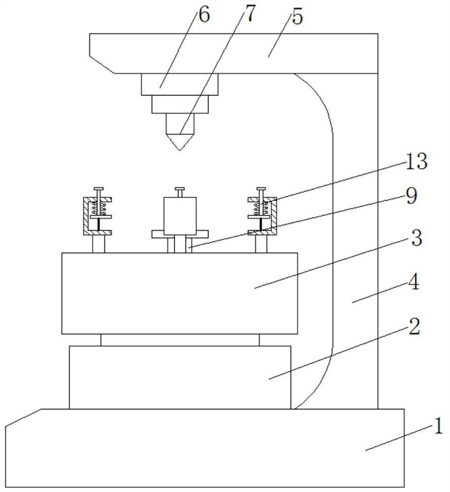
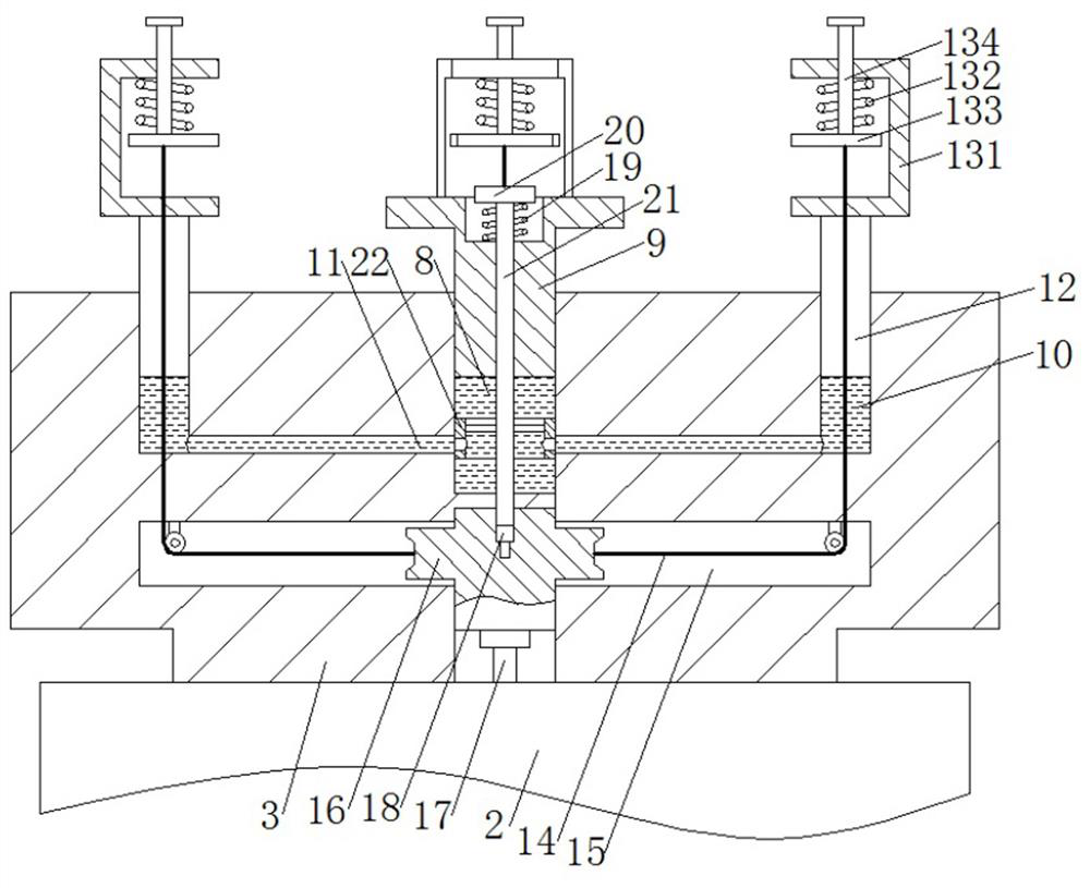
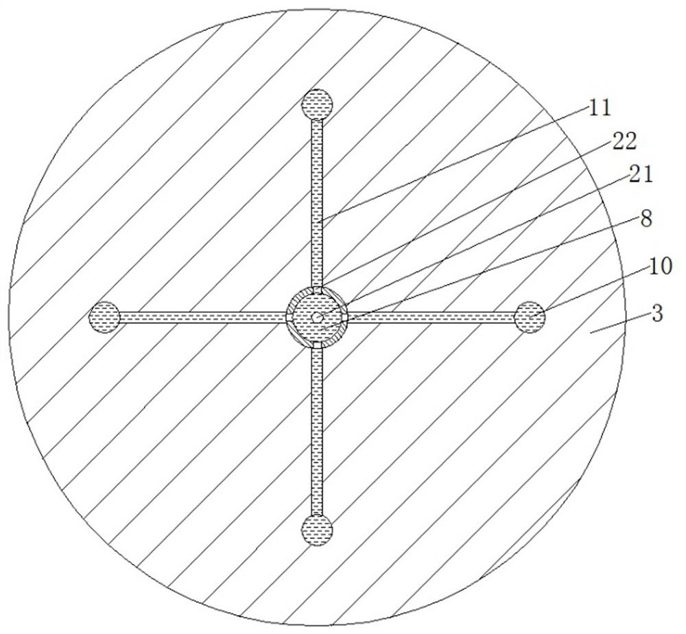
[0020] like Figure 1 to Figure 3 As shown, in the embodiment of the present invention, a hardness testing device for a photovoltaic backplane includes a base 1, the upper end of the base 1 is fixedly connected with a mounting plate 2, the upper end of the mounting plate 2 is fixedly connected with a working platform 3, and the upper end of the base 1 is fixedly connected with a working platform 3 One side is fixedly connected with a...


PUM


Abstract

The invention belongs to the technical field of hardness testing equipment, and discloses a hardness testing device for a photovoltaic backplane, comprising a base, an upper end of the base is fixedly connected with a mounting plate, and the upper end of the mounting plate is fixedly connected with a working platform. Through the arrangement of the main cavity, the auxiliary cavity, the movable rod and the sliding device, the invention can not only ensure that the upper end face of the main support plate and the bottom end face of the inner side of the C-type plate are always kept on the same horizontal line, so that the supporting area in the middle of the tested sample plate can be changed. In addition, during the detection process, the communication between the main cavity and each auxiliary cavity is blocked, so as to avoid the uneven pressure caused by the deformation of the material during the maintenance and down-pressing process. The support plate or each auxiliary support plate is displaced up and down, which affects the test results, ensuring that the main support plate and the auxiliary support plate are absolutely stationary, thereby improving the detection accuracy so that the material does not bend and deform, eliminating the influence of bending on the hardness test, improving the detection accuracy.

Description

technical field [0001] The invention belongs to the technical field of hardness testing equipment, in particular to a hardness testing device for a photovoltaic backplane. Background technique [0002] Hardness testing is an important indicator for testing the physical properties of hard materials such as plates. In short, it is the ability of the material to resist the pressing of harder objects into its surface, because the hardness test can reflect the chemical composition, organizational structure and processing technology of the material. The difference is often used as a means of supervision in all walks of life. For example, in the photovoltaic industry, the hardness of the photovoltaic backplane can determine the performance of the entire photovoltaic module, and the photovoltaic backplane is usually tested by a desktop hardness tester. On the support platform, press down the test head to press it hard to test the hardness. [0003] At present, the general desktop ...

Claims


Application Information

Patent Timeline
Patent Type & Authority Patents(China)
IPC IPC(8): H01L21/66
CPCH01L22/12Y02E10/50
Inventor 杨小龙宋琦于鹏程隋新丰田立宝程新莲杨向东
Owner 山东中策新能源有限公司
Features
  • R&D
  • Intellectual Property
  • Life Sciences
  • Materials
  • Tech Scout
  • Unparalleled Data Quality
  • Higher Quality Content
  • 60% Fewer Hallucinations
Learn More