A wheel axle disassembly and assembly equipment
A technology of equipment and axles, which is applied in the field of axle disassembly and assembly equipment, can solve problems such as unreasonable design, low work efficiency, and insufficient structure optimization, and achieve the effects of reasonable design, high work efficiency, and optimized structure
- Summary
- Abstract
- Description
- Claims
- Application Information
AI Technical Summary
Problems solved by technology
Method used
Image
Examples
Embodiment 1
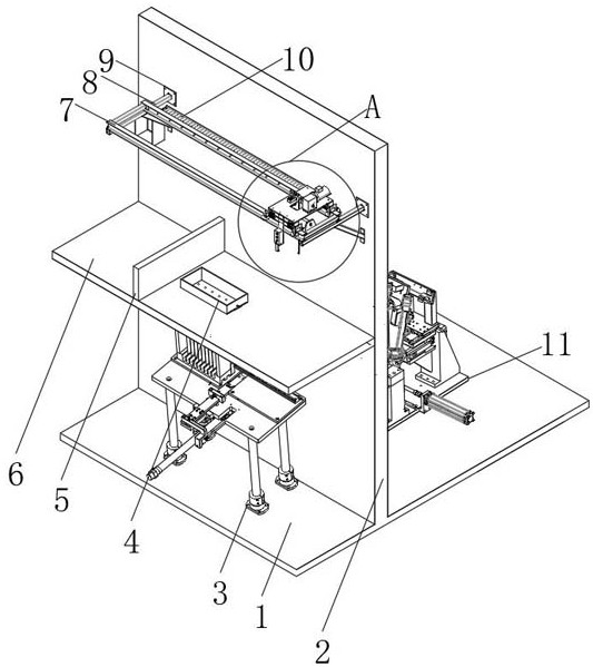
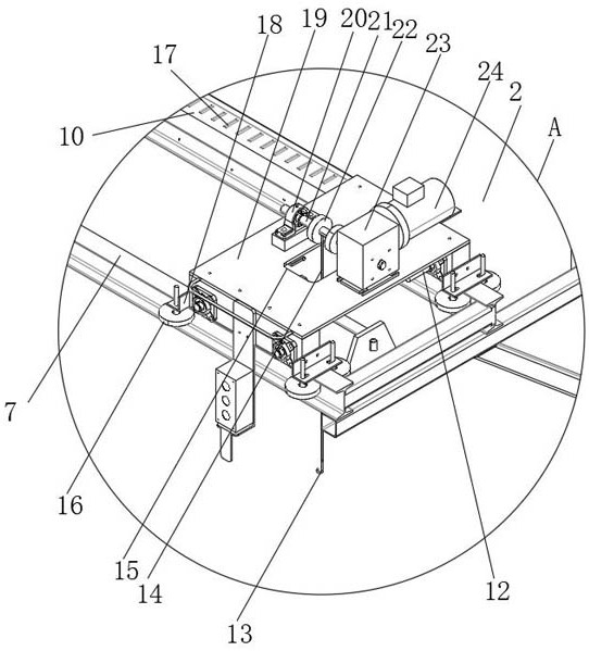
[0031] see Figures 1 to 8 , the wheel axle disassembly and assembly equipment of the preferred embodiment of the present invention includes a base plate 1, a vertical partition 2 is fixedly installed on the top of the base plate 1, and a pusher structure 3 is fixedly installed on the top of the base plate 1 and located on one side of the vertical partition 2 . A mounting and dismounting structure 11 is fixedly installed on the top of the base plate 1 and on the other side of the vertical partition 2 , and a support plate 6 is fixedly mounted on the side of the vertical partition 2 away from the mounting and dismounting structure 11 . The support plate 6 is located above the pushing structure 3 , a silo 4 is disposed on the top of the support plate 6 , and a plurality of first discharge ports are provided through the support plate 6 under the silo 4 . A vertical baffle plate 5 is fixedly installed on the top of the support plate 6 , and a displacement structure 9 is fixedly i...
Embodiment 2
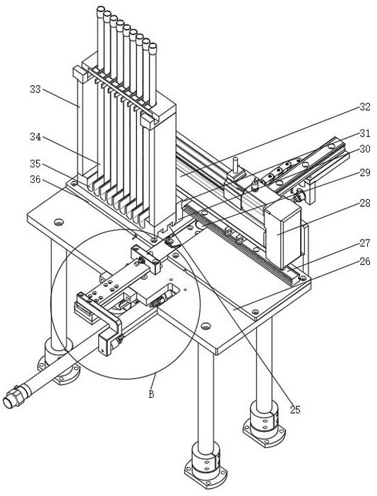
[0035] In a preferred embodiment, the pulley drive consists of two pulleys and a belt, and the two pulleys are connected by a belt drive. The pushing structure 3 includes a placing plate 26 , a backing plate 36 is fixedly installed on one side of the top of the placing plate 26 , and a sliding seat 27 is fixedly installed between the tops of the two backing plates 36 . The top of a backing plate 36 is provided with a material pipe rack 33, the bottom of the inner cavity of the material pipe rack 33 is provided with a number of discharge channels 25, the top of the material pipe rack 33 is interspersed with a number of feeding pipes 34, and the feeding pipes 34 are placed with the The insides of the grooves 35 communicate with each other. The bottom of the feed pipe 34 is fixedly installed with an inclined guide plate, and the bottom of the placement slot 35 is provided with a discharge channel 25 directly below the placement slot 35 , and the discharge channel 25 communicates ...
Embodiment 3
[0037] In a preferred embodiment, a U-shaped seat 41 and a push frame 42 are respectively fixedly installed on the top of the second push plate 40 , and a push plate 1 39 is fixedly installed at the bottom of the second push plate 40 . The inside of the horizontal box 32 is fixedly installed with an electric push rod, the telescopic end of the electric push rod is fixedly installed with a connecting short block 31, and the connecting short block 31 is fixedly connected with the connecting block 30, and the bottom of the horizontal box 32 is provided with a connecting short block 31. Compatible slides.
[0038] Further, the assembling and dismounting structure 11 includes a bottom plate 47 , a sliding plate 45 is slidably installed on the top of the bottom plate 47 , a workpiece placing rack 46 is disposed on the top of the sliding plate 45 , and a workpiece body 43 is disposed on the top of the workpiece placing rack 46 . One side of the bottom plate 47 is fixedly mounted with...
PUM
 Abstract
Description
Claims
Application Information
 - R&D
- Intellectual Property
- Life Sciences
- Materials
- Tech Scout
- Unparalleled Data Quality
- Higher Quality Content
- 60% Fewer Hallucinations
Browse by: Latest US Patents, China's latest patents, Technical Efficacy Thesaurus, Application Domain, Technology Topic, Popular Technical Reports.
© 2025 PatSnap. All rights reserved.Legal|Privacy policy|Modern Slavery Act Transparency Statement|Sitemap|About US| Contact US: help@patsnap.com


