Automatic unstacking and carrying device and method for angle steel

A handling device and angle steel technology, which is applied in the direction of object destacking, object stacking, transportation and packaging, etc., can solve the problems of heavy weight, difficult handling, and difficult hoisting of angle steel, and achieve the effect of convenient grabbing

Active Publication Date: 2022-05-27
上海众冠智能设备有限公司
View PDF10 Cites 1 Cited by
  • Summary
  • Abstract
  • Description
  • Claims
  • Application Information

AI Technical Summary

Problems solved by technology

The traditional angle steel is manually handled at the initial stage of processing, and the angle steel is heavy and slender
Difficult to carry by a single person and difficult to lift with a spreader

Method used


Image

  • Automatic unstacking and carrying device and method for angle steel
  • Automatic unstacking and carrying device and method for angle steel
  • Automatic unstacking and carrying device and method for angle steel

Examples


Embodiment 1

[0049] In a first aspect, the embodiments of the present application disclose an automatic destacking and handling device for angle steel.

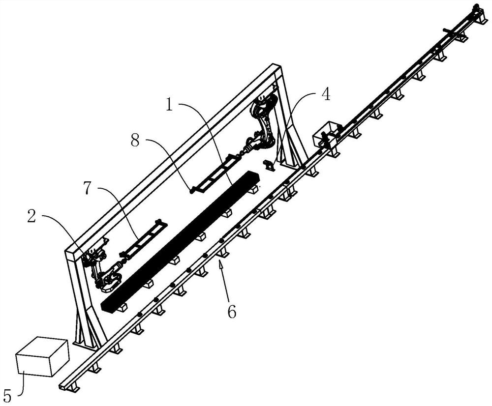
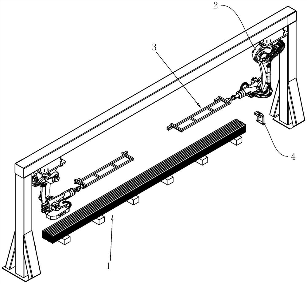
[0050] refer to figure 1 and figure 2 , an automatic destacking and handling device for angle steel, including a feeding platform 1, the feeding platform 1 is fixed on the ground, and the feeding platform 1 is a steel plate horizontally supported on the ground. The angle steel stacking type is a layer of positive V and a layer of inverted V staggered stacking.

[0051] refer to figure 1 and figure 2 , and also includes an image sensor 4, the image sensor 4 is an industrial camera, there are two image sensors 4, the two image sensors 4 are respectively arranged at both ends of the feeding platform 1, and the two image sensors 4 are fixed on the ground by steel brackets Above, the image sensor 4 is mainly used to take pictures of the end faces of the stacked angle steels.

[0052] refer to figure 1 and figure 2 , in order to facilit...

Embodiment 2

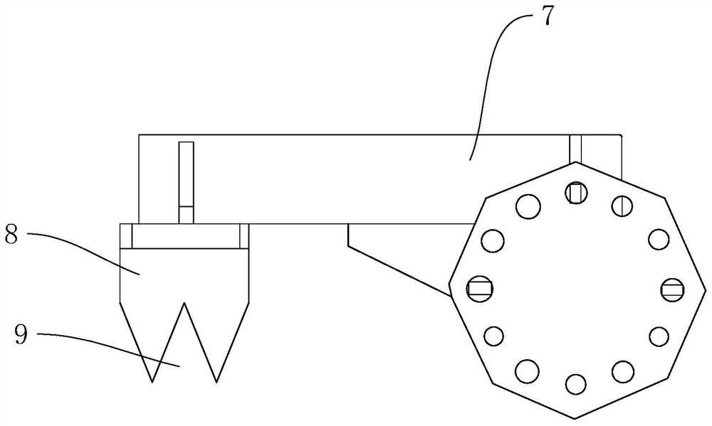
[0057] refer to Figure 4 and Figure 5 The difference between the second embodiment and the first embodiment is that the installation frame 7 is also provided with a magnetic lock piece 10 for preventing the angle steel from falling.

[0058] refer to Figure 5 , the magnetic lock 10 includes a mounting block 11, an electromagnetic tube 12, a lock lever 13 and a return spring 14. The mounting block 11 is fixed on the side wall of the electromagnetic block, and the electromagnetic tube 12 is fixed on the side wall of the mounting block 11. When the mounting frame When arranged in parallel, the axial direction of the electromagnetic tube 12 is parallel to the horizontal direction, and the mounting block 11 is provided with a mounting hole 15 which communicates with the inner cavity of the electromagnetic tube 12 . The lock rod 13 slides horizontally in the installation hole 15 , and the reset spring 14 is coaxially sleeved on the outside of the lock rod 13 .

[0059] refer t...


PUM


Abstract

The invention relates to the technical field of angle steel machining, in particular to an automatic unstacking and carrying device for angle steel. The automatic unstacking and carrying device comprises a feeding platform used for stacking the angle steel; the number of the robots is two, and the robots are located at the two ends of the feeding platform correspondingly. The gripper device is detachably arranged at the tail end of the robot arm and used for grabbing and carrying the angle steel; the two image sensors are located at the two ends of the feeding platform correspondingly and used for taking pictures of the cross sections of the angle steel stacked on the feeding platform; the control cabinet is used for receiving the cross section data sent by the image sensor, controlling the robot to adjust the position of the gripper device and accurately grab the angle steel and turn over the angle steel, and the control cabinet is electrically connected with the image sensor and the robot; according to the scheme, hoisting or manual carrying is not needed in the whole process, and robot grabbing is more convenient.

Description

technical field [0001] The present application relates to the technical field of angle steel processing, in particular to an automatic destacking and handling device and method for angle steel. Background technique [0002] At present, the section size of the equilateral angle steel of the workpiece is 40×3mm, 40×4mm, 45×4mm, 45×5mm, 50×4mm, 50×5mm, 50×6mm, and the uniform length of incoming materials is 9000mm. The heaviest single The root angle steel is 40.2Kg. The incoming state is that the first layer of angle steel is in a row in an inverted V state; the second layer is in a row in a positive V state, which is staggered with the first layer, and the third layer of angle steel is in a row in an inverted V state, and is staggered with the second layer. , in turn in a stacking type, with a maximum of 32 layers in a single stacking type. [0003] In the actual processing process of angle steel, it needs to be cut to length, chamfered at both ends, and processing of mounti...

Claims


Application Information

Patent Timeline
Patent Type & Authority Applications(China)
IPC IPC(8): B23Q7/04B23Q17/24B65G61/00
CPCB23Q7/043B23Q17/2409B65G61/00B65G2201/0217
Inventor 刘宇晴逄政
Owner 上海众冠智能设备有限公司
Why Eureka
Try Eureka