
Eureka
For R&D, Eureka makes reading and utilizing patents & technical documents easy.
Eureka AIR
Designed for self-driven R&D workflows. Generate viable solutions, solve complex R&D challenges, empower your innovation with AI.

Eureka Materials
Designed for material experts only. Revolutionize your material R&D, from search, analyze, to developing new materials.

TechResearch
Generate reliable direction feasibility study reports for your R&D in just a few steps.

TechSeek
Discover and master advanced knowledge NOW. Basics, ideas, possibilities, all at once.

TechMind
As an expert in R&D Theories, TechMind can generates customized viable solutions instantly.

TechRisk
Analyze your overall solution with one click, know your potential R&D risks in advance.

TechMonitor
Get weekly tech updates, stay abreast of the latest tech innovations and key insights.
Supporting frame for shaft part machining
A technology of shaft parts and support frame, which is applied in the field of shaft parts processing, can solve the problems of inconvenient shaft parts feeding, high transportation cost, potential safety hazards, etc., and achieve the effect of ensuring synchronization and good collection effect.
- Summary
- Abstract
- Description
- Claims
- Application Information
AI Technical Summary
Problems solved by technology
Method used
Image

Examples
Embodiment 1
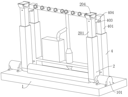
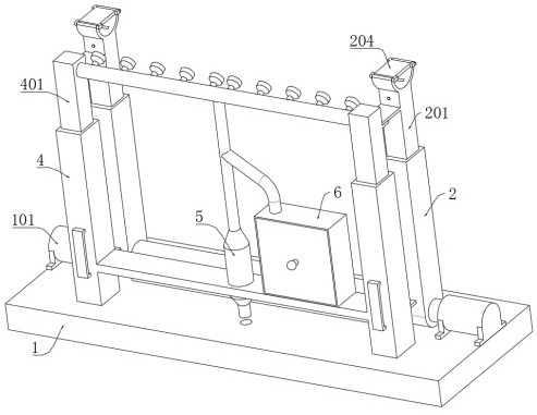
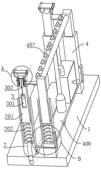
[0035] refer to Figure 1-10 , a support frame for shaft parts processing, comprising: a base 1; a rotating support 2 rotatably connected to the base 1; a sliding support 201 slidably connected to the rotating support 2; An arc-shaped frame 203 is fixedly connected to one end of the frame; the bracket spring 202 is fixedly connected to the sliding bracket 201 and the rotating bracket 2 at both ends; the rotating plate 204 connected to the arc-shaped frame 203 is rotated; Removably connected to the arc-shaped frame 203; the pressing plate 206 slidably connected in the arc-shaped frame 203 is used to clamp the shaft parts; the inflatable component is used to fill the rotating bracket 2 with gas to adjust the sliding bracket 201. Height, a drive motor 101 is fixedly connected to the base 1 , and the rotating bracket 2 is fixedly connected to the output end of the drive motor 101 .
[0036] When using the device, when the shaft parts are transported to the ground on the side of t...
Embodiment 2
[0065] refer to Figure 1-10 , a support frame for shaft parts processing, when using this device, when the shaft parts are transported to the ground on the side of the base 1, the drive motor 101 drives the rotating support 2 to rotate, so that the rotating support 2 is away from the base. One end of 1 is attached to the ground. When the shaft parts are loaded and fixed, the gravity of the counterweight block 3 can make the sliding bracket 201 and the rotating bracket 2 relatively far away, even if the slope of the rotating bracket 2 is low, it is convenient to Rolling feeding of shaft parts;
[0066] At this time, the latch 205 is pulled out, so that the rotating plate 204 can be rotated and attached to the ground. At this time, the rotating plate 204 can play a guiding role, which is convenient for rolling the shaft parts from the rotating plate 204 to the arc frame 203;
[0067] After the movement is completed, the rotating plate 204 is rotated and reset and fixed by the ...
PUM
 Abstract
Description
Claims
Application Information
 - R&D Engineer
- R&D Manager
- IP Professional
- Industry Leading Data Capabilities
- Powerful AI technology
- Patent DNA Extraction
Browse by: Latest US Patents, China's latest patents, Technical Efficacy Thesaurus, Application Domain, Technology Topic, Popular Technical Reports.
© 2024 PatSnap. All rights reserved.Legal|Privacy policy|Modern Slavery Act Transparency Statement|Sitemap|About US| Contact US: help@patsnap.com