Industrial robot automatic tool workpiece calibration method

A technology of industrial robots and automatic tools, applied in the direction of manufacturing tools, manipulators, program-controlled manipulators, etc., can solve problems such as operational errors, low efficiency, and poor precision, and achieve the effect of improving contact accuracy

Pending Publication Date: 2022-05-27
重庆智能机器人研究院
View PDF22 Cites 0 Cited by
  • Summary
  • Abstract
  • Description
  • Claims
  • Application Information

AI Technical Summary

Problems solved by technology

In practical application, the accuracy of this method is poor: the alignment state of the tip is recognized by naked eyes, the hard plastic in charge of human beings plays a dominant role, and the alignment state of experienced technicians is good;
[0005] 2. In the prior art, there is an automatic tool workpiece calibration method for industrial robots. When using it, beginners will have misalignment and need to repeat multiple alignment calibrations; the efficiency is low;
[0006] 3. In the prior art, there is an automatic tool workpiece calibration method for industrial robots. When in use, the whole process is manually operated to check and align the calibration tip, and repeat the operation many times. Operation errors are very prone to cause collisions.

Method used


Image

  • Industrial robot automatic tool workpiece calibration method
  • Industrial robot automatic tool workpiece calibration method
  • Industrial robot automatic tool workpiece calibration method

Examples


Embodiment 1

[0045] The edge finder assembly can be replaced with higher cost ruby ​​machine contacts:

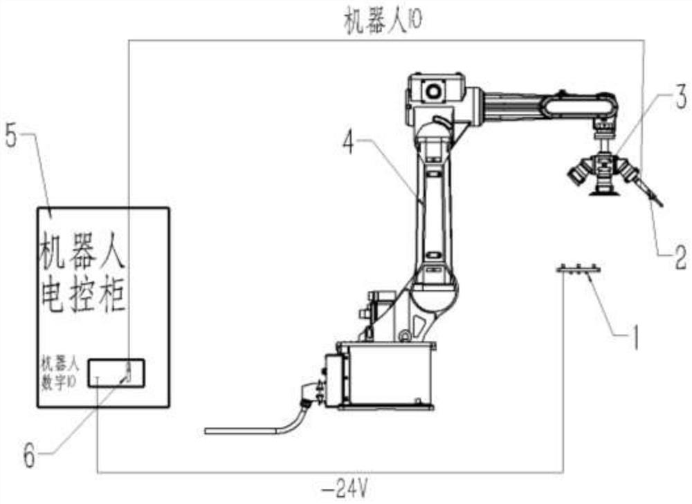
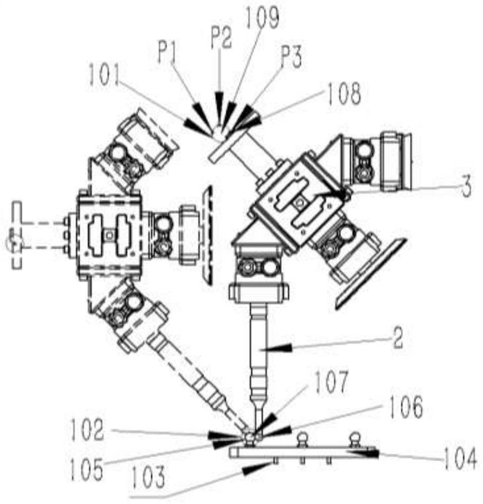
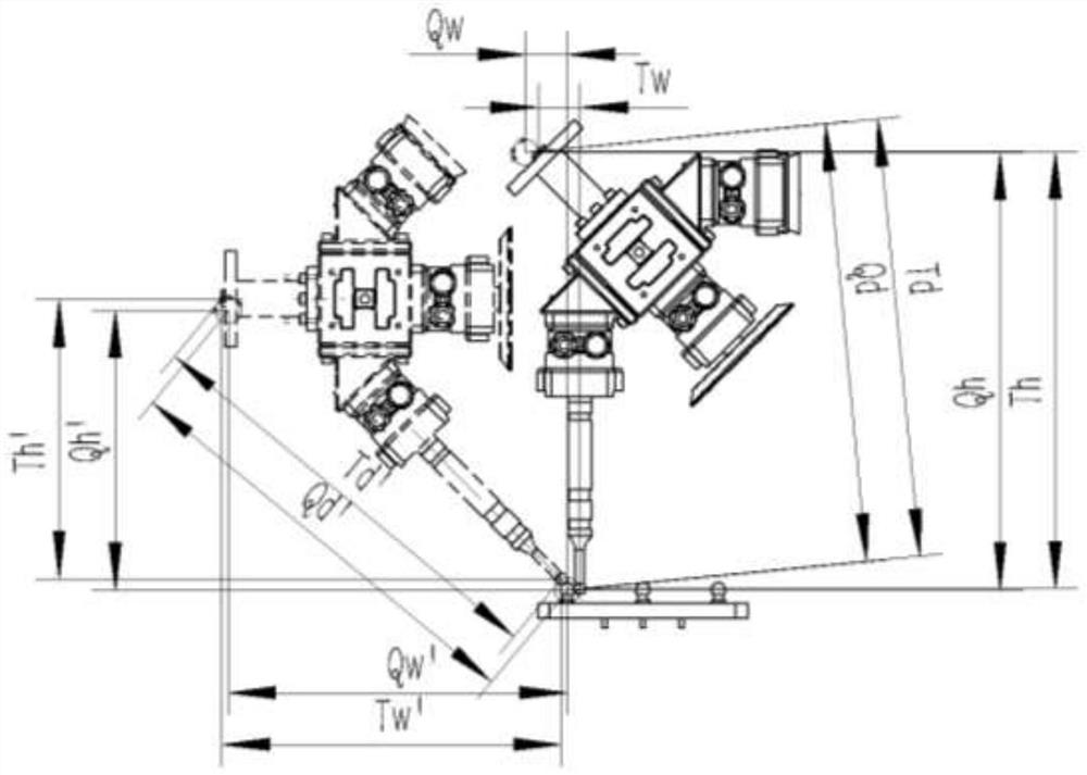
[0046] Step 1: Connect all hardware parts according to the structure and connection relationship. Step 2: Operate the 4-industrial robot to make the 2-edge finder point in front of the 105-reference ball. At this time, the 2-edge finder is not in contact with the 105-reference ball. Step 3: Run the robot automatic calibration program, the robot will automatically find the 105-reference ball with a fixed posture, so that the 2-edge finder is in contact with the 105-reference ball. Step 4: 4- The robot automatically runs in a fixed posture and contacts the 105-reference ball three times, and records the three points P1, P2, and P3 respectively. Step 5: According to the three points P1, P2 and P3, find the center of the circle and calculate the coordinates of the center of the 109-robot running track. Step 6: Change 4- Robot Pose. Step 7: Repeat step 2, repeat step 3, repeat step 4, rep...

Embodiment 2

[0048] The reference ball is a calibration reference standard for machine tool processing, which can be processed by yourself or used by purchasing standard parts from suppliers:

[0049] Step 1: Connect all hardware parts according to the structure and connection relationship. Step 2: Operate the 4-industrial robot to make the 2-edge finder point in front of the 105-reference ball. At this time, the 2-edge finder is not in contact with the 105-reference ball. Step 3: Run the robot automatic calibration program, the robot will automatically find the 105-reference ball with a fixed posture, so that the 2-edge finder is in contact with the 105-reference ball. Step 4: 4- The robot automatically runs in a fixed posture and contacts the 105-reference ball three times, and records the three points P1, P2, and P3 respectively. Step 5: According to the three points P1, P2 and P3, find the center of the circle and calculate the coordinates of the center of the 109-robot running track....


PUM


Abstract

The invention discloses an industrial robot automatic tool workpiece calibration method. The industrial robot automatic tool workpiece calibration method comprises the following working steps that firstly, all hardware parts are connected according to structures and connection relations; 2, operating an industrial robot 4 to enable an edge finder 2 to be at a point position in front of the reference ball 105, wherein the edge finder 2 is not in contact with the reference ball 105 at the moment; and step 3, running an automatic calibration program of the robot, and enabling the robot to automatically search the 105-reference ball in a fixed posture, so that the 2-edge finder is in contact with the 105-reference ball. Fourthly, the robot (4) automatically runs in a fixed posture and makes contact with the reference ball (105) for three times, and the points P1, P2 and P3 are recorded respectively. And 5, according to the three points P1, P2 and P3, the circle center is solved, and 109-robot moving trajectory center coordinates are calculated. And 6, the posture of the robot 4 is changed. The positions of the centers of circles of the two balls are solved by utilizing multiple tangency of the two balls, point contact during contact can be ensured by ball contact, and the contact precision is improved to the maximum extent.

Description

technical field [0001] The invention relates to the technical field of industrial robots, in particular to an industrial robot automatic tool workpiece calibration method. Background technique [0002] With the development of society, machines have replaced manual work in various automated operations, which has developed rapidly. In the use of robots, it is necessary to let the robot know what kind of tool it has, which is the definition of the tool center for robot control. And what the robot is going to do, the robot workpiece coordinate definition. [0003] In the prior art, an industrial robot automatic tool workpiece calibration method has shortcomings: [0004] 1. Patent document CN109760108A discloses an industrial robot suction cup tool hand calibration and positioning method in the field of industrial robot technology. To disassemble, control the cylinder to drive the calibration shaft fixed on the first guide plate to move down, so that the calibration head at th...

Claims


Application Information

Patent Timeline
Patent Type & Authority Applications(China)
IPC IPC(8): B25J9/16
CPCB25J9/1653B25J9/1669
Inventor 焦志勇郭金霖吕春年钟源庹奎曾海郑登华王贤福
Owner 重庆智能机器人研究院
Why Eureka
Try Eureka