
Squeezing type carton film laminating machine capable of avoiding bubbles

A laminating machine, extrusion-type technology, applied in the field of extrusion-type carton laminating machine, can solve the problems of insufficient lamination safety, separation of film and carton board, and weak bonding, etc., to ensure stability The effect of moving, avoiding bubbles or bulges

Pending Publication Date: 2022-05-27
裴经冠
View PDF8 Cites 0 Cited by
  • Summary
  • Abstract
  • Description
  • Claims
  • Application Information

AI Technical Summary

Problems solved by technology

[0005] The purpose of the present invention is to provide a squeeze-type carton laminating machine that avoids air bubbles, to solve the existing carton laminating machines on the market proposed by the above-mentioned background technology. The film is attached to the carton. During the lamination process, air bubbles or bulges are likely to occur between the carton board and the film, which affects the overall lamination effect and appearance of the carton. The bonding between the boards is not firm, the film is separated from the carton board, and the purpose of covering the film cannot be achieved. Safety issues

Method used


Image

  • Squeezing type carton film laminating machine capable of avoiding bubbles
  • Squeezing type carton film laminating machine capable of avoiding bubbles
  • Squeezing type carton film laminating machine capable of avoiding bubbles

Examples


Embodiment 1

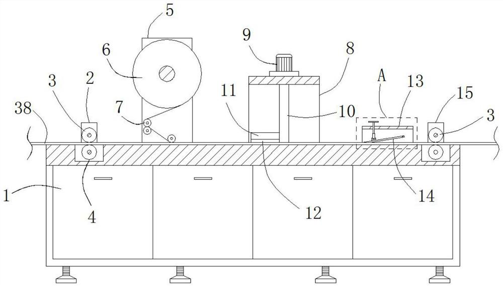
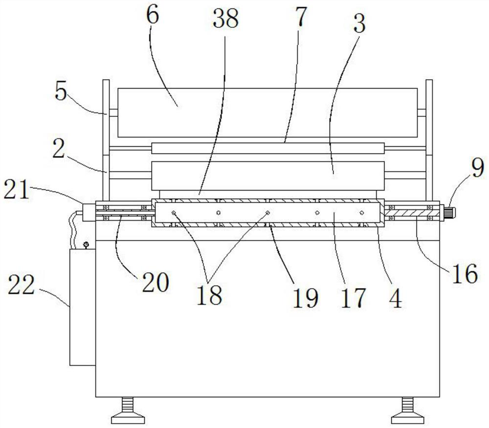
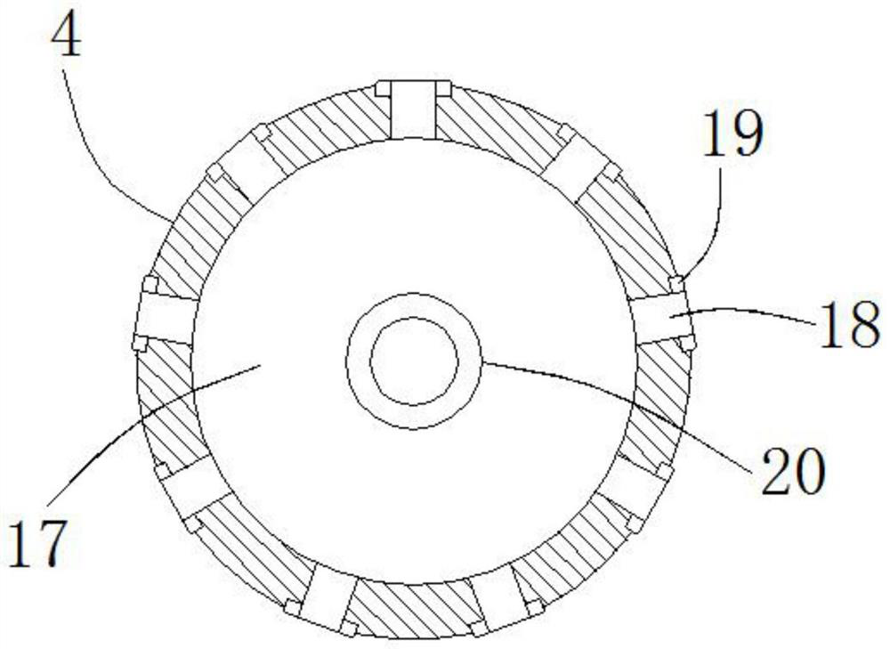
[0034]An extrusion-type carton laminating machine for avoiding air bubbles includes a laminating machine body 1, an input mechanism 2 is arranged on the upper part of one side of the laminating machine body 1, and a horizontally arranged driven roller 3 is arranged above the inner side of the input mechanism 2. , a rotatable driving roller 4 is embedded in the upper end surface of the laminator body 1 under the driven roller 3, a carton board 38 is passed between the driven roller 3 and the driving roller 4, and the rear side of the input mechanism 2 is provided with a The laminating mechanism 5 for laminating the carton board 38 is provided with a laminating roller 6 on the inner upper part of the laminating mechanism 5, and a tension roller 7 for unwinding the film is provided below the laminating roller 6. The side is provided with a scraping and defoaming mechanism 8 for pressing and spreading the film. The rear side of the scraping and defoaming mechanism 8 is provided wit...

Embodiment 2

[0036] The difference between this embodiment and Embodiment 1 is that two motors 9 are provided on the upper part of the top of the scraping and defoaming mechanism 8 , and the output end of the motors 9 is connected to the turret 10 below the scraping and defoaming mechanism 8 . The lower end is welded with a horizontally arranged leveling frame 11. The lower end surface of the leveling frame 11 is provided with an upper receiving slot 30 for installing the electromagnetic coil 32. The lower part of the coil 32 is provided with a magnetic metal frame 33 that can slide up and down inside the upper receiving slot 30 , a spring 31 is arranged between the upper part of the two sides of the magnetic metal frame 33 and the upper receiving slot 30 , and the lower end of the magnetic metal frame 33 is glued with a spring 31 . The scraping strip 12 for scraping the film horizontally, the scraping and defoaming mechanism 8 between the two turrets 10 are welded with two vertically arran...

Embodiment 3

[0038] The difference between this embodiment and the first embodiment is that the inner side of the pressing mechanism 13 is provided with a pressing frame 14 that can rotate at one end. The upper part of the other end of the frame 14 is provided with a connecting block 26, the upper part of the connecting block 26 is connected with the rotating shaft of the rotating wire sleeve 27, and the rotating wire sleeve 27 is threadedly connected with the lower end of the adjusting frame 34 through the threaded hole at the top thereof, and the adjusting frame 34 is connected with the pressing The top bearing of the mechanism 13 is connected, and the lower part of the pressing frame 14 at one end of the connecting block 26 is provided with a fixing groove 35, and a pressing bar 28 for pressing the film downward is installed inside the fixing groove 35. The inner part of the pressing bar 28 There are elastic metal strips 36 extending therethrough. Both ends of the elastic metal strips 36...


PUM


Abstract

The extrusion type carton film laminating machine comprises a film laminating machine body, an input mechanism, a film laminating mechanism, a film laminating roller and a tension roller, the input mechanism is arranged on the upper portion of one side of the film laminating machine body, and a horizontally-arranged driven roller is arranged on the upper portion of the inner side of the input mechanism; a rotatable driving roller is embedded in the upper end face of the film laminating machine body below the driven roller, a tension roller used for unfolding a film is arranged below the film laminating roller, a slicking and defoaming mechanism used for pressing and unfolding the film is arranged on the rear side of the film laminating mechanism, a pressing mechanism is arranged on the rear side of the slicking and defoaming mechanism, and the film laminating mechanism is arranged on the upper end face of the film laminating machine body. Two horizontal driven rollers are arranged on the inner side of the output mechanism, and a carton board is inserted between the two driven rollers in a penetrating mode. According to the extrusion type carton film laminating machine capable of avoiding the bubbles, corresponding mechanisms are arranged before and after film laminating of a carton board, a film can be attached to the carton board, and the bubbles or bumps can be avoided.

Description

technical field [0001] The invention relates to the technical field of carton laminating machines, in particular to an extrusion type carton laminating machine that avoids air bubbles. Background technique [0002] The carton laminating machine is to attach a layer of film to the outer surface of the existing ordinary carton board to make the carton waterproof. A carton laminating machine with a thickness of A conveyor belt is sleeved on the outside of the box body, the conveyor belt is arranged on the upper side of the box body, the upper end of the box body is fixed with an adjustment frame, the upper end of the adjustment frame is rotatably connected with an adjustment rod, and the inside of the adjustment frame is slidably connected with a fixed The main purpose of the block is to facilitate the lamination of different thicknesses and to facilitate the cutting of the film. However, when it is used, there are the following problems: [0003] 1. When laminating the cart...

Claims


Application Information

Patent Timeline
Patent Type & Authority Applications(China)
IPC IPC(8): B29C63/02
CPCB29C63/02B29C63/0004
Inventor 裴经冠
Owner 裴经冠
Learn More