
Spiral compression device for straw

A technology of compression device and straw, applied in presses, manufacturing tools, biofuels, etc., can solve problems such as damage to the workshop environment, potential safety hazards, and short-term reverse injection of steam, so as to ensure workshop safety and facilitate liquid drainage and exhaust. Effect

Pending Publication Date: 2022-05-27
江苏智用仁恒新能源装备有限公司
View PDF0 Cites 0 Cited by
  • Summary
  • Abstract
  • Description
  • Claims
  • Application Information

AI Technical Summary

Problems solved by technology

[0003] In actual production and operation, due to the influence of uneven or interrupted incoming materials, screw shaft wear, check valve failure and other conditions, the steam in the pressure chamber of the tubular reactor will be temporarily back-sprayed. Spraying and back-spraying steam not only damage the workshop environment, but also pose safety hazards

Method used


Image

  • Spiral compression device for straw
  • Spiral compression device for straw

Examples


Embodiment Construction

[0024] The technical solutions of the present invention will be further elaborated below with reference to specific embodiments and accompanying drawings.

[0025] In the following, only certain exemplary embodiments are briefly described. As those skilled in the art would realize, the described embodiments may be modified in various different ways, all without departing from the spirit or scope of the embodiments of the present invention. Accordingly, the drawings and description are to be regarded as illustrative in nature and not restrictive.

[0026] In the description of the embodiments of the present invention, it should be understood that the orientation or positional relationship indicated by the terms "length", "inside", etc. is based on the orientation or positional relationship shown in the accompanying drawings, and is only for the convenience of describing the embodiments of the present invention and simplify the description, rather than indicating or implying th...


PUM


Abstract

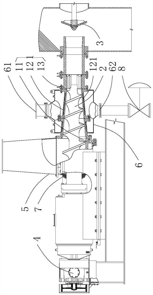
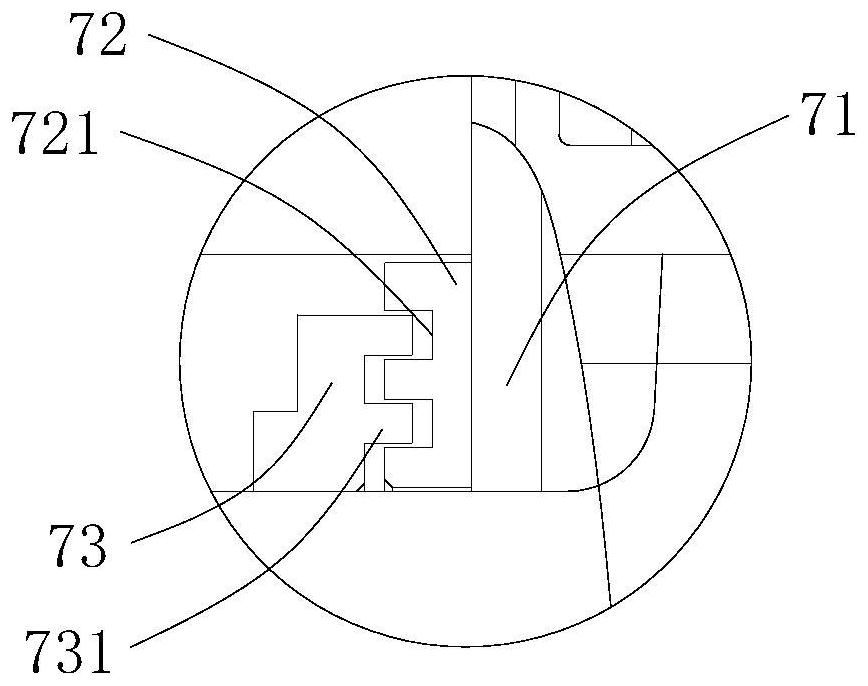
The invention discloses a spiral compression device for straw. The spiral compression device comprises a barrel, a spiral shaft, a check valve arranged on the outer side of one end of the barrel and a driving motor arranged on the outer side of the other end of the barrel and used for driving the spiral shaft to rotate. The barrel comprises a feeding section, a compression section and a material plug section which are communicated in sequence, a plurality of through holes are formed in the compression section, and the density of the through holes is gradually increased in the straw conveying direction; the spiral compression device further comprises a feeding elephant trunk communicated with the feeding section, a sealing cover annularly arranged on the outer side of the compression section and a sealing mechanism arranged between the other end of the barrel and the spiral shaft. The sealing cover is provided with an exhaust port and a liquid outlet. The spiral compression device further comprises a switch valve used for controlling opening and closing of the liquid outlet. And the check valve and the switch valve are used for blocking one end of the barrel and the liquid outlet respectively when the current of the driving motor is reduced to a set value. By means of the spiral compression device, continuous compression and discharging of straw can be achieved, and meanwhile potential safety hazards existing in a workshop during steam reverse spraying can be avoided.

Description

technical field [0001] The invention relates to a screw compression device for straw. Background technique [0002] The existing screw compression device for straw relies on the reduction of the volume of the pitch space, so that the straw raw material is gradually compressed along the conveying direction, and the compressed straw raw material forms a straw material plug at the end of the screw. As the straw material is propelled continuously, the straw material plug is continuously formed, and the straw material plug at the front end is further pushed into the tubular reactor, which can not only continuously push the straw material under normal pressure into the reactor, but also use the straw material plug. Ensure the tightness of the feed port under the pressure condition of the reactor. [0003] In actual production and operation, due to uneven or interrupted incoming materials, screw shaft wear, check valve failure, etc., the short-term reverse injection of steam in th...

Claims


Application Information

Patent Timeline
IPC IPC(8): B30B15/00B30B9/30
CPCB30B15/0017B30B9/3003B30B9/3064Y02E50/10B30B9/3089B30B9/3039
Inventor 葛念超沈桔儿吴杰
Owner 江苏智用仁恒新能源装备有限公司
Learn More