Tandem type brake master cylinder with adjustable pre-tightening force for electric control brake system

A technology of electronically controlled braking and brake master cylinder, applied in the direction of brake transmission, brakes, vehicle components, etc., can solve the problem of large volume, vacuum booster that cannot meet the braking requirements of new energy vehicles, and the structure of the brake master cylinder Complicated and other issues, to reduce the difficulty of processing and installation, convenient production, small footprint effect

Inactive Publication Date: 2022-05-27
BEIJING YINGCHUANG HUIZHI TECH
View PDF7 Cites 1 Cited by
  • Summary
  • Abstract
  • Description
  • Claims
  • Application Information

AI Technical Summary

Problems solved by technology

[0002] With the expansion of the new energy vehicle market, traditional vacuum boosters cannot meet the braking requirements of new energy vehicles. Under the market demand, new energy vehicles have a working mode of decoupling braking action and braking execution. , the braking action is the action of the driver stepping on the brake pedal, and the braking execution is the action of the friction plate and the brake disc or brake drum
In the process of action force component, the driver's braking does not directly act on the brake, but collects the braking signal through the position sensor to identify the driver's intention. The brake master cylinder is the main component of the pedal input. The current brake master The structure of the cylinder is relatively complex and occupies a large volume

Method used


Image

  • Tandem type brake master cylinder with adjustable pre-tightening force for electric control brake system
  • Tandem type brake master cylinder with adjustable pre-tightening force for electric control brake system
  • Tandem type brake master cylinder with adjustable pre-tightening force for electric control brake system

Examples


Embodiment 1

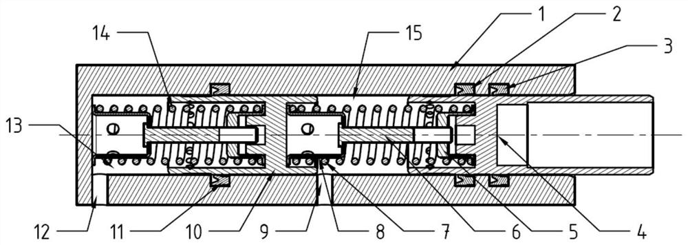
[0027] Example one, as figure 1 As shown, a tandem brake master cylinder with adjustable pre-tightening force for an electronically controlled brake system includes a housing 1 with a primary piston 4 and a secondary piston 10 in the housing 1. The primary piston 4 and the secondary piston 10 are arranged in parallel. The front ends of the primary piston 4 and the secondary piston 10 are respectively equipped with a primary spring 7 and a secondary spring 14. The sealing ring 3 is sealed, the secondary piston 10 is sealed by the third sealing ring 11, the primary spring 7 is fixed and preloaded by the first spring holder 5 and the second spring holder 8, and the first spring holder The second spring holder 8 is connected with the guide rod 6 through threads, and the fixing structure of the secondary spring 14 is the same as that of the primary spring 4 .

[0028] During normal movement, when the driver steps on the pedal, the first-stage piston 4 starts to move, and the liqui...


PUM


Abstract

The pre-tightening force adjustable tandem type brake master cylinder comprises a shell, a first-stage piston and a second-stage piston are arranged in the shell, the first-stage piston and the second-stage piston are arranged in parallel, a first-stage spring and a second-stage spring are installed at the front end of the first-stage piston and the front end of the second-stage piston respectively, and the first-stage spring and the second-stage spring are arranged in parallel. The first-stage piston is sealed by the first sealing ring and the second sealing ring, a pedal feeling is simulated through the pedal simulator, and the electric master cylinder conducts braking action. When the electric master cylinder breaks down, when a driver steps on a pedal, the first-stage piston and the second-stage piston start to move, and liquid in a first cavity composed of the shell, the first-stage piston and the second-stage piston and liquid in a second cavity composed of the shell and the second-stage piston flow to the wheel cylinder through a liquid outlet and a liquid outlet for braking. And the springs connected with the two pistons have the same structure, so that the production is convenient, the occupied volume is small, and the cost increase caused by different adjustment structures of vehicle types is avoided.

Description

technical field [0001] The invention belongs to the technical field of automobile braking, and in particular provides a series-type brake master cylinder used in an electric control braking system with adjustable pre-tightening force. Background technique [0002] With the expansion of the new energy vehicle market, traditional vacuum boosters cannot meet the braking needs of new energy vehicles. Under the market demand, a working mode of decoupling braking action and braking execution has appeared on new energy vehicles. , The braking action is the action of the driver stepping on the brake pedal, and the braking execution is the action of the friction pad and the brake disc or the brake drum. In the process of action component force, the driver's brake does not directly act on the brake, but collects the brake signal through the position sensor to identify the driver's intention. The brake master cylinder is the main component of the pedal input. The cylinder structure is...

Claims


Application Information

Patent Timeline
Patent Type & Authority Applications(China)
IPC IPC(8): B60T13/16
CPCB60T13/161B60T13/168
Inventor 刘海超魏凌涛付佳鑫
Owner BEIJING YINGCHUANG HUIZHI TECH
Why Eureka
Try Eureka