
Spray pipe for fixing thermal shrinkage label

A nozzle and label technology, which is applied in the field of nozzles for fixing heat shrinkable labels, can solve the problems of easy blocking of nozzle holes, reduction of high-temperature gaseous spray, and wrinkles, so as to improve the pre-fixing effect and increase the pre- The effect of fixing the area and improving the heat shrinkage effect

Pending Publication Date: 2022-05-27
HANGZHOU ZHONGYA MACHINERY CO LTD
View PDF0 Cites 0 Cited by
  • Summary
  • Abstract
  • Description
  • Claims
  • Application Information

AI Technical Summary

Problems solved by technology

[0003] In the existing production, when the label is heat-shrinkable and bonded, it is generally heated by spraying a high-temperature gaseous spray through the nozzle. Since the nozzle hole is directly opened on the nozzle pipe, the cooling liquid water droplets formed on the outer wall of the nozzle are easy to block the nozzle hole. , which will lead to a decrease in the amount of high-temperature gaseous spray, which will affect the heat shrinkage effect of the label
In addition, when the high-temperature gaseous spray is sprayed from the nozzle hole, the liquid water droplets will be sprayed to the label. Due to the high temperature of the liquid water droplets, the part of the label is easily heated and wrinkled under the action of the liquid water droplets, which seriously affects the label. Shrink effect

Method used


Image

  • Spray pipe for fixing thermal shrinkage label
  • Spray pipe for fixing thermal shrinkage label
  • Spray pipe for fixing thermal shrinkage label

Examples


Embodiment 1

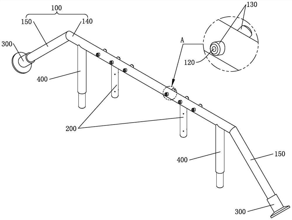
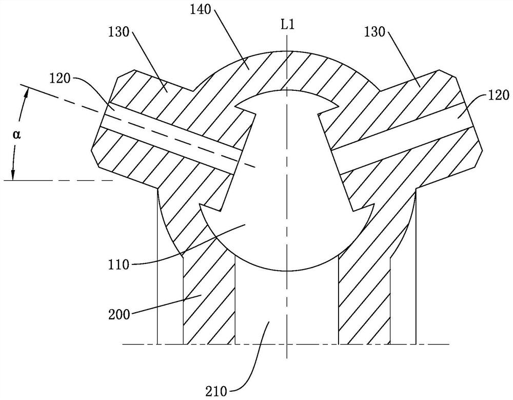
[0030] like Figure 1 to Figure 4 As shown, the first embodiment of the present invention provides a nozzle for fixing a heat shrinkable label, including a main pipe 100 provided with a main channel 110 , and a first air injection hole 120 communicating with the main channel 110 is formed on the main pipe 100 . The main pipe 100 is provided with a boss 130 protruding obliquely upward, and the first air injection hole 120 is provided at the boss 130 . The nozzle also includes a branch pipe 200 connected to the bottom of the main pipe 100. The branch pipe 200 is provided with a branch flow channel 210 and a second air injection hole 220. One end of the branch flow channel 210 is communicated with the main flow channel 110, and the other end is closed. Road 210 is connected.

[0031] An obliquely upwardly protruding boss is set on the main pipe, and the first air injection hole is located at the boss. Because the liquid water droplets formed by cooling are mainly distributed on ...


PUM


Abstract

The invention discloses a spray pipe for fixing a thermal shrinkage label, and belongs to the technical field of filling equipment, the spray pipe comprises a main pipe provided with a main flow channel, the main pipe is provided with a first air injection hole communicated with the main flow channel, the main pipe is provided with a boss protruding upwards in an inclined mode, the first air injection hole is formed in the boss, and the spray pipe further comprises a branch pipe connected to the bottom of the main pipe. The branch pipe is provided with a branch flow channel and a second air injection hole, one end of the branch flow channel communicates with the main flow channel, the other end of the branch flow channel is closed, and the second air injection hole communicates with the branch flow channel. The liquid water beads formed by cooling are mainly distributed on the outer wall of the main pipe, so that the liquid water beads can be prevented from blocking the first gas spraying holes, the spraying amount of the high-temperature gaseous spray at the first gas spraying holes is ensured, meanwhile, the liquid water beads are prevented from being sprayed to the thermal shrinkage label, and the thermal shrinkage effect of the thermal shrinkage label is improved. During working, the second gas spraying holes and the first gas spraying holes spray high-temperature gaseous spray at the same time, so that the thermal shrinkage label can be uniformly heated and shrunk, and the thermal shrinkage effect of the thermal shrinkage label can be improved.

Description

technical field [0001] The invention relates to the technical field of filling equipment, in particular to a nozzle for fixing heat shrinkable labels. Background technique [0002] The outside of the cup body of the existing canned food is generally fixed with a label. Due to the different materials of the label, the combination between the label and the cup body can generally be divided into two types: thermoplastic lamination and heat shrink lamination. In the thermoplastic bonding method, the label is placed in the mold cavity of the cup body in a curled state before the cup body is extruded. When the sheet is heated and extruded in the mold cavity to form the cup body, the label is heated and attached to outside of the cup. In the heat shrink bonding method, the cup body has been formed, the continuously arranged labels are cut into smaller labels and sleeved on the outside of the formed cup body, and then the label is heated to make the label stick to the outside of th...

Claims


Application Information

Patent Timeline
Patent Type & Authority Applications(China)
IPC IPC(8): B65C7/00B65B53/06B65C3/08
CPCB65C7/00B65B53/06B65C3/08
Inventor 史中伟史正樊杰飞
Owner HANGZHOU ZHONGYA MACHINERY CO LTD
Learn More