Mechanical speed-limiting elevator safety tongs with high safety

A high-safety, mechanical technology, applied in the field of safety gear, can solve the problems that the safety gear cannot clamp the guide rail, does not have dust cleaning at the jaws of the safety gear, and affects safety, so as to reduce the impact sound and increase the friction coefficient , the effect of saving resources

Pending Publication Date: 2022-05-27
南通中力科技有限公司
View PDF12 Cites 1 Cited by
  • Summary
  • Abstract
  • Description
  • Claims
  • Application Information

AI Technical Summary

Problems solved by technology

"However, this device does not have the function of cleaning the jaws of the safety gear. The accumulation of dust at the jaws of the safety gear will cause the safety gear to fail to clamp the guide rail, and then the elevator car will continue to slide, affecting safety.

Method used


Image

  • Mechanical speed-limiting elevator safety tongs with high safety
  • Mechanical speed-limiting elevator safety tongs with high safety
  • Mechanical speed-limiting elevator safety tongs with high safety

Examples


Embodiment 1

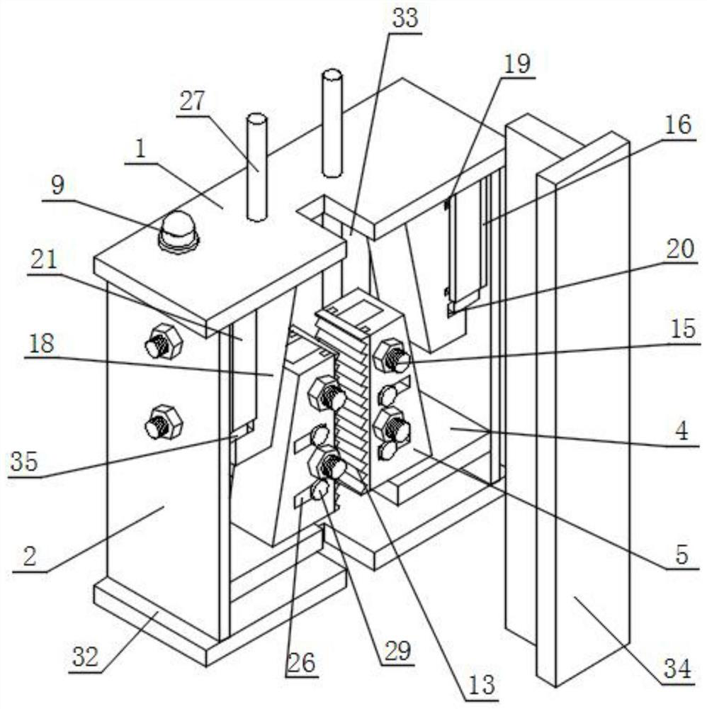
[0043] like figure 1 and Figure 8 As shown in the figure, a mechanical speed-limiting elevator safety gear with high safety includes a top plate 1, a side plate 2, a connecting plate 3, a square plate 4, a clamp body 5 and a fixing nail 6, and two groups are installed at the bottom of the top plate 1. Side panels 2 arranged side by side, two sets of side panels 2 adjacent to one side of the outer wall are installed with connecting plates 3, two sets of connecting panels 3 adjacent to one side of the outer wall is installed with vertical plates 7, the front of the vertical plates 7 is installed with a distance Sensor 8, an alarm 9 is installed on the top of the top plate 1, and the alarm 9 and the distance sensor 8 are electrically connected;

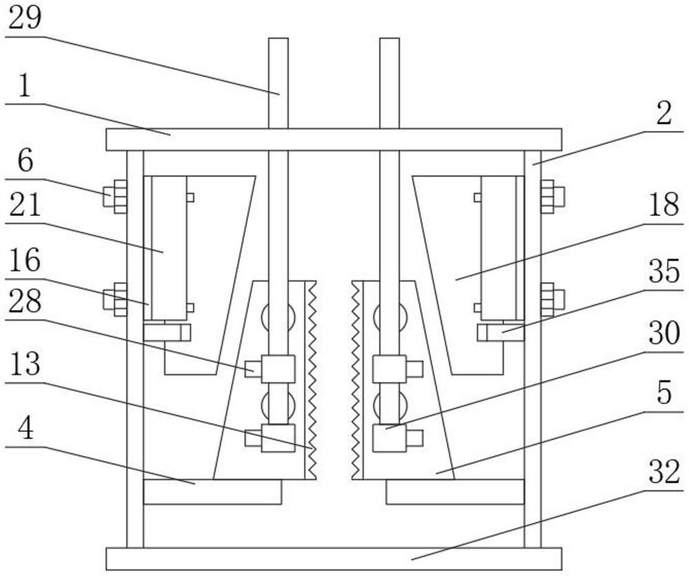
[0044] Specifically, a frame can be formed between the top plate 1 , the bottom plate 32 and the two sets of side plates 2 , which can then be used to install other components in the device, and at the same time provide a certain exter...

Embodiment 2

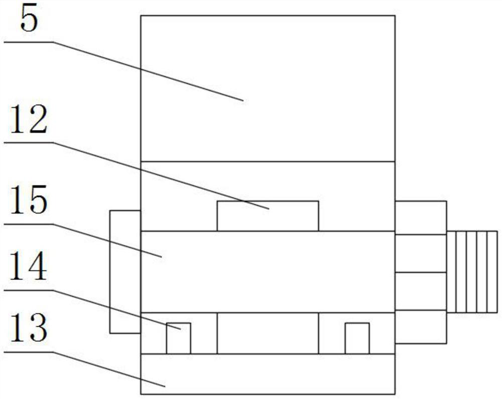
[0050] like figure 1 and Image 6 As shown, one side outer wall of the forceps body 5 is provided with a fitting groove 10, and one side outer wall of the forceps body 5 is provided with two groups of grooves 11 arranged in front and rear, and the two groups of grooves 11 are respectively located in front of the fitting groove 10 and In the rear, a fitting block 12 is installed on the inner wall of the fitting groove 10 , a toothed plate 13 is installed on one outer wall of the fitting block 12 , and one outer wall of the toothed plate 13 is fitted with the outer wall of the clamp body 5 , and the toothed groove is One side of the outer wall of the plate 13 is installed with two sets of engaging strips 14 arranged in front and rear, and the outer walls of the two sets of engaging strips 14 are respectively fitted with the inner walls of the two sets of grooves 11. The locking nails 15 are arranged up and down, and the front surfaces of the locking nails 15 penetrate through t...

Embodiment 3

[0053] like figure 2 , image 3 and Figure 4 As shown, an integrated plate 16 is installed on one end of the fixing nail 6, and two sets of springs 17 arranged up and down are installed on one side of the integrated plate 16. The end of the spring 17 away from the integrated plate 16 is installed with a wedge 18. The front of the wedge 18 Two sets of moving grooves 19 arranged up and down are provided on the back and the back side, and an engaging groove 20 is provided on the outer wall of one side of the wedge block 18 close to the integrated board 16 .

[0054] One side outer wall of the integrated board 16 is installed with two sets of edge wrapping boards 21 arranged in front and rear, and two sets of upper and lower clamping blocks are installed on the front of one set of edge wrapping boards 21 and the back of the other set of edge wrapping boards 21. 22 , and the outer walls of the four groups of engaging blocks 22 are respectively fitted with the inner walls of the...


PUM


Abstract

The high-safety mechanical speed-limiting elevator safety tongs comprise a top plate, side plates, connecting plates, a square plate, a tongs body and fixing nails, the two side plates arranged side by side are installed at the bottom of the top plate, the connecting plates are installed on the outer walls of the adjacent sides of the two side plates, and vertical plates are installed on the outer walls of the adjacent sides of the two connecting plates; a distance sensor is installed on the front face of the vertical plate, and an alarm is installed on the top of the top plate. Square plates are installed on the outer walls of the adjacent sides of the two sets of side plates. By arranging the distance monitoring device, when the distance between the guide rail and the distance sensor exceeds a set range, the alarm can make a set sound, distance data of the distance sensor can be transmitted to an elevator master control room, a tooth groove plate in the device has the disassembling and assembling functions, replacement is convenient, meanwhile, material resources can be saved, and when the device is braked, the device is convenient to disassemble and assemble. Impact can be relieved through the spring, the device has the movable dust blowing function, and it can be ensured that no dust is accumulated on the tooth groove plate.

Description

technical field [0001] The invention relates to the technical field of safety gears, in particular to a mechanical speed-limiting elevator safety gear with high safety. Background technique [0002] Elevators are commonly used transportation equipment, especially car elevators used in high-rise buildings, and the safety of elevators is becoming more and more important. Safety gear is an important part of the elevator safety system. The elevator safety gear device is in the speed limiter. Under control, when the elevator speed exceeds the speed limit set by the speed governor, or when the suspension rope breaks and loosens, it is a safety device that stops the car in an emergency and clamps it on the guide rail. [0003] The defects of the existing safety gear are: [0004] 1. The patent document CN207258947U discloses a two-way speed-limiting safety gear for an elevator, which "comprises a fixed guide rail, a frame body, an upper braking unit, a lower braking unit, a brakin...

Claims


Application Information

Patent Timeline
Patent Type & Authority Applications(China)
IPC IPC(8): B66B5/22B66B5/00B66B5/02B08B5/02
CPCB66B5/22B66B5/0025B66B5/02B08B5/02
Inventor 金锋
Owner 南通中力科技有限公司
Why Eureka
Try Eureka