Thermal power plant denitration wastewater treatment device
A technology for wastewater treatment and thermal power plants, which is applied in the direction of backflow water treatment, water/sewage multi-stage treatment, water/sludge/sewage treatment, etc. It can solve problems such as incomplete wastewater treatment, achieve convenient maintenance, high reaction efficiency, The effect of improving efficiency
- Summary
- Abstract
- Description
- Claims
- Application Information
AI Technical Summary
Problems solved by technology
Method used
Image

Examples
Example Embodiment
[0039] Example 1
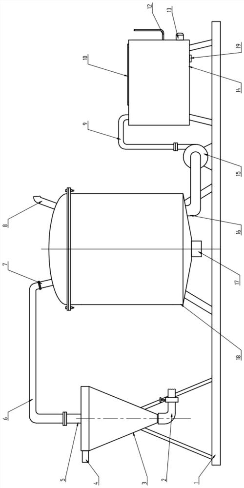
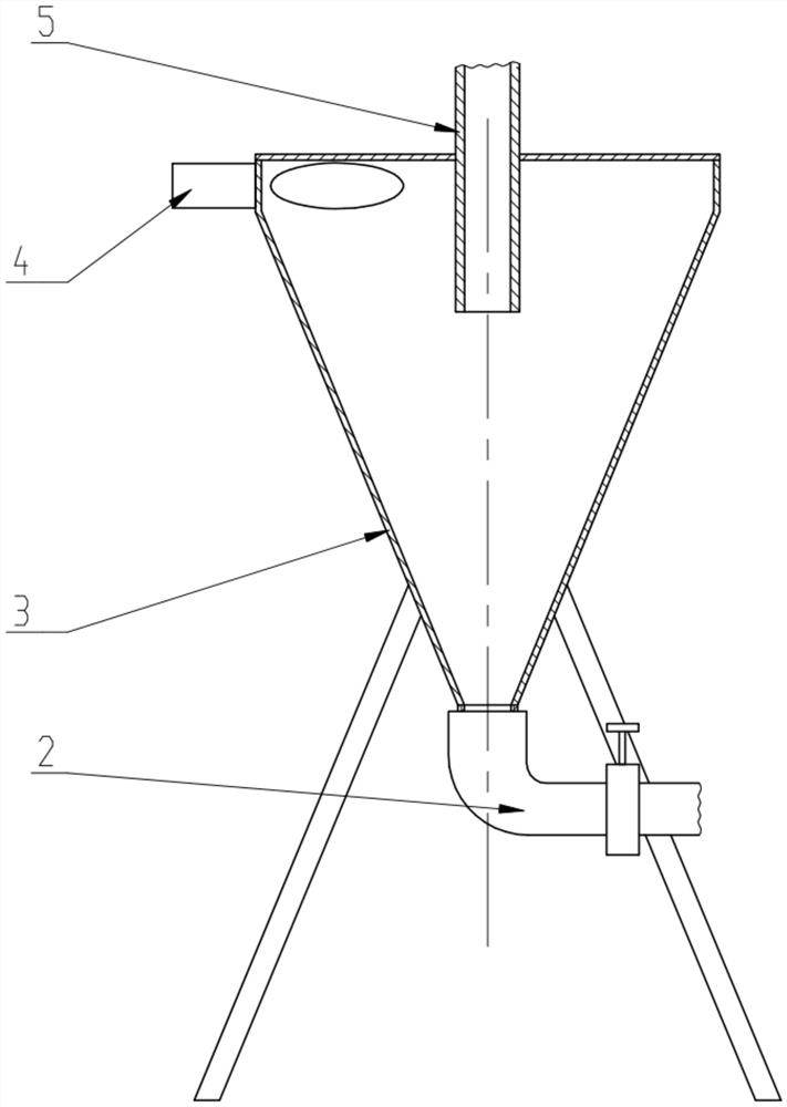
[0040] like figure 1 , figure 2 , image 3 and Figure 4 As shown in the figure, a thermal power plant denitration wastewater treatment device includes a rectangular base 1 that is fixedly arranged on the ground and formed by group welding of section steel, a cyclone that is fixedly connected to the base 1 by bolts in sequence from left to right, Vertical cylindrical closed sedimentation tank and rectangular closed filter box.
[0041] The upper part of the sedimentation tank is a semi-ellipsoidal head 20 , and the lower part of the sedimentation tank is a barrel-shaped tank body 18 . The tank body 18 and the head 20 are fixedly connected by flanges. The inlet pipe 7 is welded on the top left part of the sealing head 20, the dosing pipe 8 is welded on the top right part of the sealing head 20, and the dosing pipe 8 is provided with a valve. The bottom of the tank 18 is provided with an outlet pipe 16 .
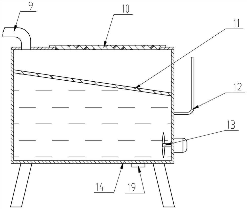
[0042] The filter box includes a rectangular b...
Example Embodiment
[0052] Example 2
[0053] like Figure 5 As shown, the difference between this embodiment and Embodiment 1 is:
[0054] The upper part of the sedimentation tank is provided with a first cavity 25 and a second cavity 24 which are independent and closed from each other, the first cavity 25 is located above the second cavity 24, and the first cavity 25 is connected to the inlet pipe 7 The second cavity 24 communicates with the dosing pipe 8 , the bottom of the first cavity 25 is provided with a first downward nozzle, and the bottom of the second cavity 24 is provided with a second downward nozzle.
[0055] The bottom surface of the head 20 is welded with a bottom plate 21 , a partition plate 26 welded with the head 20 is arranged above the bottom plate 21 , the first cavity 25 is located above the partition plate 26 , and the second cavity 24 Below the partition plate 26, the inlet pipe 7 is welded through the head 20, the baffle plate 26 and the head 20 are welded through the ...
Example Embodiment
[0057] Example 3
[0058] like Image 6 As shown, the difference between this embodiment and Embodiment 1 is:
[0059] The right side of the tank body 18 is provided with a circulation pipe, and the circulation pipe is provided with a circulation pump 27 .
[0060] After the circulating pump 27 is started, the waste water in the tank 18 is circulated up and down, so that the waste water and the flocculant added in the dosing pipe 8 are mixed and reacted.
[0061] Since the circulation pump 27 and the circulation pipe are arranged outside the tank body 18, the maintenance can be easily performed when the circulation pump 27 fails.
PUM
 Abstract
Description
Claims
Application Information
 - R&D Engineer
- R&D Manager
- IP Professional
- Industry Leading Data Capabilities
- Powerful AI technology
- Patent DNA Extraction
Browse by: Latest US Patents, China's latest patents, Technical Efficacy Thesaurus, Application Domain, Technology Topic.
© 2024 PatSnap. All rights reserved.Legal|Privacy policy|Modern Slavery Act Transparency Statement|Sitemap