V-shaped steel column and construction method thereof
A construction method and section steel technology, applied in the directions of columns, pillars, pier columns, etc., can solve the problems of instability and collapse of V-shaped steel column installation, complex structure installation accuracy, etc., and achieve the effect of ensuring structural safety.
- Summary
- Abstract
- Description
- Claims
- Application Information
AI Technical Summary
Problems solved by technology
Method used
Image

Examples
Embodiment 1
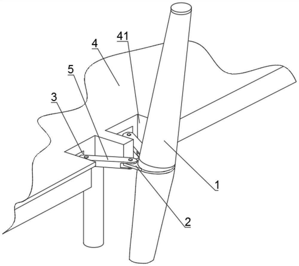
[0040] This embodiment 1 provides a V-shaped steel column, such as Figure 1 to Figure 6 shown, including:
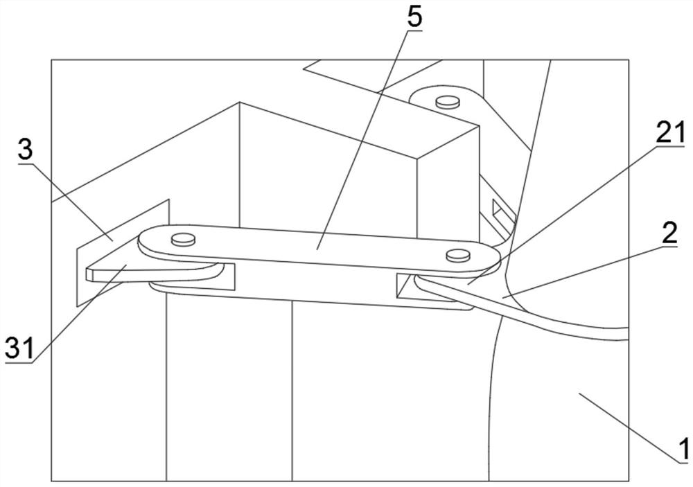
[0041] The first connecting piece 2: the first connecting piece 2 is arranged in the middle of the column body 1, and the first connecting piece 2 includes two first connecting lugs 21 with an included angle;
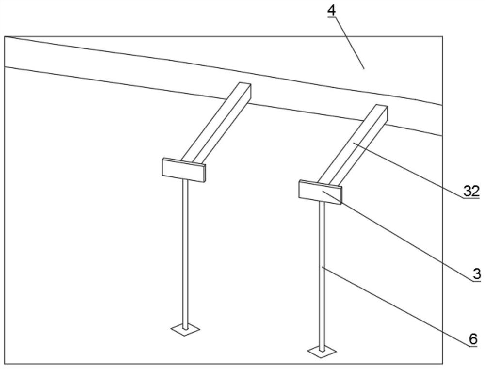
[0042] Pre-embedded panel 3: The pre-embedded panel 3 is pre-embedded on the floor structure 4, and the floor structure 4 is provided with two adjacent pre-embedded grooves 41, and the bottoms of the two pre-embedded grooves 41 are both Pre-embedded boards 3 are pre-embedded, and second connection lugs 31 are fixed on both of the pre-embedded boards 3;
[0043] Second connecting piece 5: the two first connecting pieces 2 are provided with second connecting pieces 5, and the second connecting pieces 5 are respectively pinned to the first connecting lugs 21 and the second connecting lugs 31;
[0044] The top of the column 1 is inclined in the direction away from ...
Embodiment 2
[0049] This embodiment 2 is further optimized on the basis of embodiment 1, such as Figure 5 As shown, a construction method of a V-shaped steel column is provided, which includes the following steps:
[0050] S1: pour the floor structure 4, and pre-embed the embedded board 3 on the floor structure 4;
[0051] S2: Prepare the column body 1, and install the first connector 2 horizontally in the middle of the column body 1 according to the inclination angle of the column body 1;
[0052] S3: Then build a temporary support at the pre-installation position of the column 1;
[0053] S4: After the temporary support is constructed, the column body 1 is hoisted at the pre-installation position, and the column body 1 is supported by the temporary support;
[0054] S5: Then weld the second connection lug plate 31 on the embedded plate 3, and pin the second connection piece 5 to the first connection lug plate 21 and the second connection lug plate 31 respectively;
[0055] S6: The te...
Embodiment 3
[0060] This Embodiment 3 is further optimized on the basis of Embodiment 2, and is used as another implementation manner.
[0061] In this embodiment, a plurality of lifting lugs 7 are arranged in sequence along the length direction of the column body 1 ; in order to adjust the angle of the column body 1 when the column body 1 is hoisted, in this solution, the length direction of the column body 1 is adjusted. A plurality of lifting lugs 7 are arranged on the top in turn, and are hoisted by a crane. Before hoisting, an inverted chain is used to adjust the installation angle of the column body 1, which is convenient for positioning.
[0062] In this embodiment, the temporary support includes a support frame body 8, the support frame body 8 is fixed on the ground, and a sliding positioning template 9 is provided on the top of the supporting frame body 8, and the sliding positioning template 9 includes a positioning platform 91 and The sliding plate 92, the positioning platform 9...
PUM
 Abstract
Description
Claims
Application Information
 - R&D
- Intellectual Property
- Life Sciences
- Materials
- Tech Scout
- Unparalleled Data Quality
- Higher Quality Content
- 60% Fewer Hallucinations
Browse by: Latest US Patents, China's latest patents, Technical Efficacy Thesaurus, Application Domain, Technology Topic, Popular Technical Reports.
© 2025 PatSnap. All rights reserved.Legal|Privacy policy|Modern Slavery Act Transparency Statement|Sitemap|About US| Contact US: help@patsnap.com