
Emergency rescue slip assembly with bidirectional locking function and rescue system thereof

An assembly and functional technology, applied in the direction of drill pipe, casing, wellbore/well components, etc., can solve problems such as disappearance of jacking force, loosening or opening of slips, increased unforeseen risks in emergency operations, etc., to improve The effect of locking ability, ensuring safety and emergency operations, and ensuring the synchronization of switching actions

Pending Publication Date: 2022-05-27
河北华北石油荣盛机械制造有限公司
View PDF0 Cites 0 Cited by
  • Summary
  • Abstract
  • Description
  • Claims
  • Application Information

AI Technical Summary

Problems solved by technology

[0003] However, if the blowout or well kick rescue is successful, the upper force acting on the slip assembly will disappear after there is no pressure at the wellhead, and the slip seat will move down again under the gravity of the upper emergency well control equipment, prompting Slips are loose or open, this phenomenon will increase unforeseen risks to subsequent rescue operations
Due to many uncertain factors in the emergency rescue process, in order to achieve safe construction, the equipment must be locked and controlled under the action of two directions of force (upper force and equipment gravity) during emergency rescue, while the existing slips The device can only be locked in one direction

Method used


Image

  • Emergency rescue slip assembly with bidirectional locking function and rescue system thereof
  • Emergency rescue slip assembly with bidirectional locking function and rescue system thereof
  • Emergency rescue slip assembly with bidirectional locking function and rescue system thereof

Examples


Embodiment Construction

[0037] The technical solutions in the embodiments of the present invention will be clearly and completely described below with reference to the accompanying drawings in the embodiments of the present invention. Obviously, the described embodiments are only a part of the embodiments of the present invention, rather than all the embodiments. Based on the embodiments of the present invention, all other embodiments obtained by those of ordinary skill in the art without creative efforts shall fall within the protection scope of the present invention.

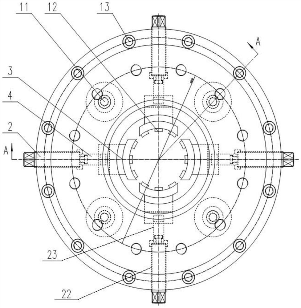
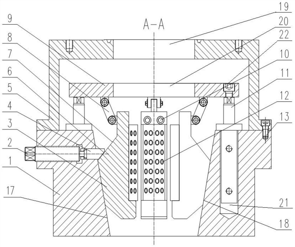
[0038] see attached figure 1 to the attached figure 2 , the embodiment of the present invention discloses an emergency rescue slip assembly with a two-way locking function, comprising:

[0039] The slip seat 1; the side wall of the inner hole of the slip seat 1 is an inverted conical inclined surface 17; the top edge of the slip seat 1 is fixedly connected with a slip connection cover 5, and the top surface of the slip connection c...


PUM


Abstract

The invention discloses an emergency rescue slip assembly with a bidirectional locking function and an emergency rescue system thereof. The side wall of an inner hole of a slip bowl of the slip assembly is an inverted conical inclined surface; the top edge of the slip bowl is fixedly connected with a slip connecting cover; the lifting plate is connected to the top edge of the slip bowl through a telescopic mechanism; the slip body is arranged in an inner hole of the slip bowl in a surrounding mode. The top end of the slip body is hinged to the lower surface of the lifting plate through a connecting rod, and the outer side wall of the slip body is provided with a slip body outer inclined face and a slip body outer wedge-caulking inclined face which are attached to the conical inclined face in a sliding mode. The radial clamping mechanism can penetrate through the side wall of the slip bowl to move in the radial direction of the slip bowl and abut against the wedge-caulking slope outside the slip bowl. The emergency rescue system comprises emergency rescue well control equipment and a slip assembly installed at the bottom end of the emergency rescue well control equipment. The invention aims to enable emergency rescue equipment not to be influenced by upward jacking force and equipment gravity during emergency rescue operation, to form a bidirectional locking working state, and to be reliably locked with a wellhead sleeve all the time, so as to realize safe emergency rescue operation.

Description

technical field [0001] The invention relates to the technical field of drilling well control emergency rescue equipment, and more particularly to an emergency rescue slip assembly with a two-way locking function and a rescue system thereof. Background technique [0002] During exploration and development drilling operations, if a well kick or blowout occurs, it is likely to cause accidents such as personal injury or equipment damage. During the blowout rescue operation, it is necessary to re-establish the wellhead, and install and fix the rescue well control equipment to the wellhead to carry out rescue operations. After the installation is completed, the rescue well control equipment will generate a large jacking force under the action of the wellhead pressure, which requires the slip assembly installed at the lower part of the rescue well control equipment and the wellhead casing to be reliably locked. The emergency well control equipment is firmly connected with the wellh...

Claims


Application Information

Patent Timeline
Patent Type & Authority Applications(China)
IPC IPC(8): E21B19/10E21B41/00
CPCE21B19/10E21B41/0021E21B41/00
Inventor 张建蒋光强侯国庆郭雪郑强李三平屈志明宋涛张贺臣李浩浩刘辉索振华
Owner 河北华北石油荣盛机械制造有限公司
Features
  • Generate Ideas
  • Intellectual Property
  • Life Sciences
  • Materials
  • Tech Scout
  • Unparalleled Data Quality
  • Higher Quality Content
  • 60% Fewer Hallucinations
Learn More