Mask nose bridge strip performance detection equipment

A testing equipment and mask technology, applied in the field of mask nose bridge performance testing equipment, can solve the problem of not being able to detect the bending resistance of the mask nose bridge, and achieve the effects of convenient bending operation, avoiding flanging and strong practicability

Pending Publication Date: 2022-05-27
刘桂兰
View PDF1 Cites 1 Cited by
  • Summary
  • Abstract
  • Description
  • Claims
  • Application Information

AI Technical Summary

Problems solved by technology

[0005] In order to overcome the shortcomings that the existing nose strip detection technology cannot detect the bending resistance of the nose strip of the mask, the technical problem to be solved is: provide a performance testing equipment for the nose strip of the mask that can detect the bending resistance

Method used


Image

  • Mask nose bridge strip performance detection equipment
  • Mask nose bridge strip performance detection equipment
  • Mask nose bridge strip performance detection equipment

Examples


Embodiment 1

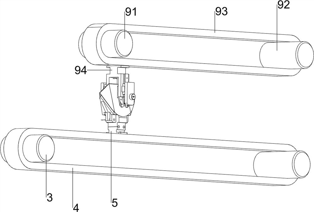
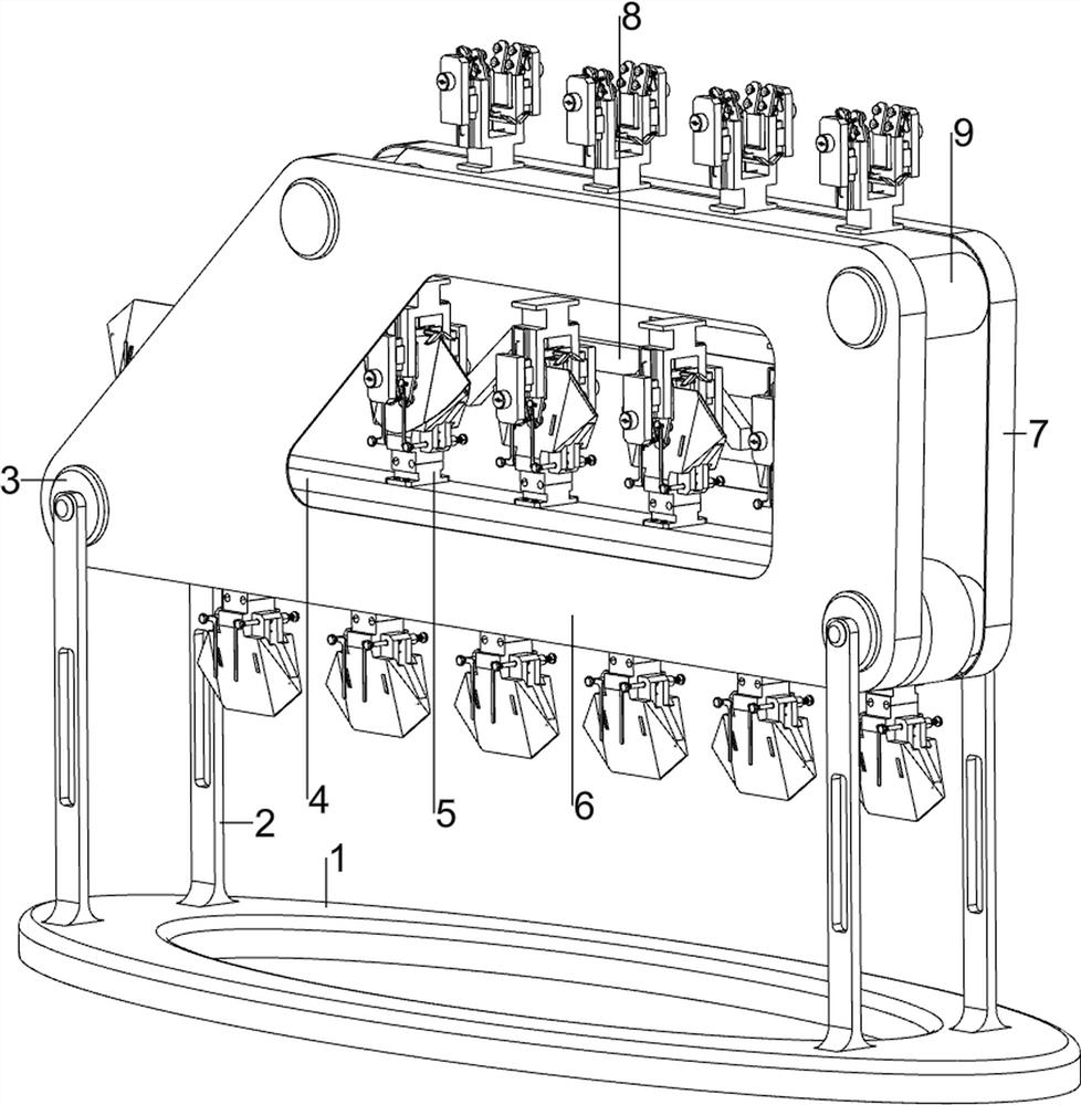
[0037] A mask nose bridge performance testing equipment, such as figure 1 , figure 2 , image 3 and Figure 4 As shown, including support frame 1, support rod 2, first roller 3, first conveyor belt 4, mask mold 5, first shell 6, second shell 7, long rod 8, unqualified mask take-away mechanism 9 and In the nose bridge test mechanism 10, the top left and right sides of the support frame 1 are symmetrically welded with support rods 2 front and rear, and the upper parts of the two support rods 2 on the same side in the longitudinal direction are connected with a first roller 3 by means of bearings, and the first roller 3 A first conveyor belt 4 is wound in between, the mask molds 5 are evenly spaced on the first conveyor belt 4, a first shell 6 is rotatably connected between the front sides of the first rollers 3, and the rear sides of the first rollers 3 are connected. A second shell 7 is connected in a rotary manner, and a long rod 8 is provided in the middle of the first sh...

Embodiment 2

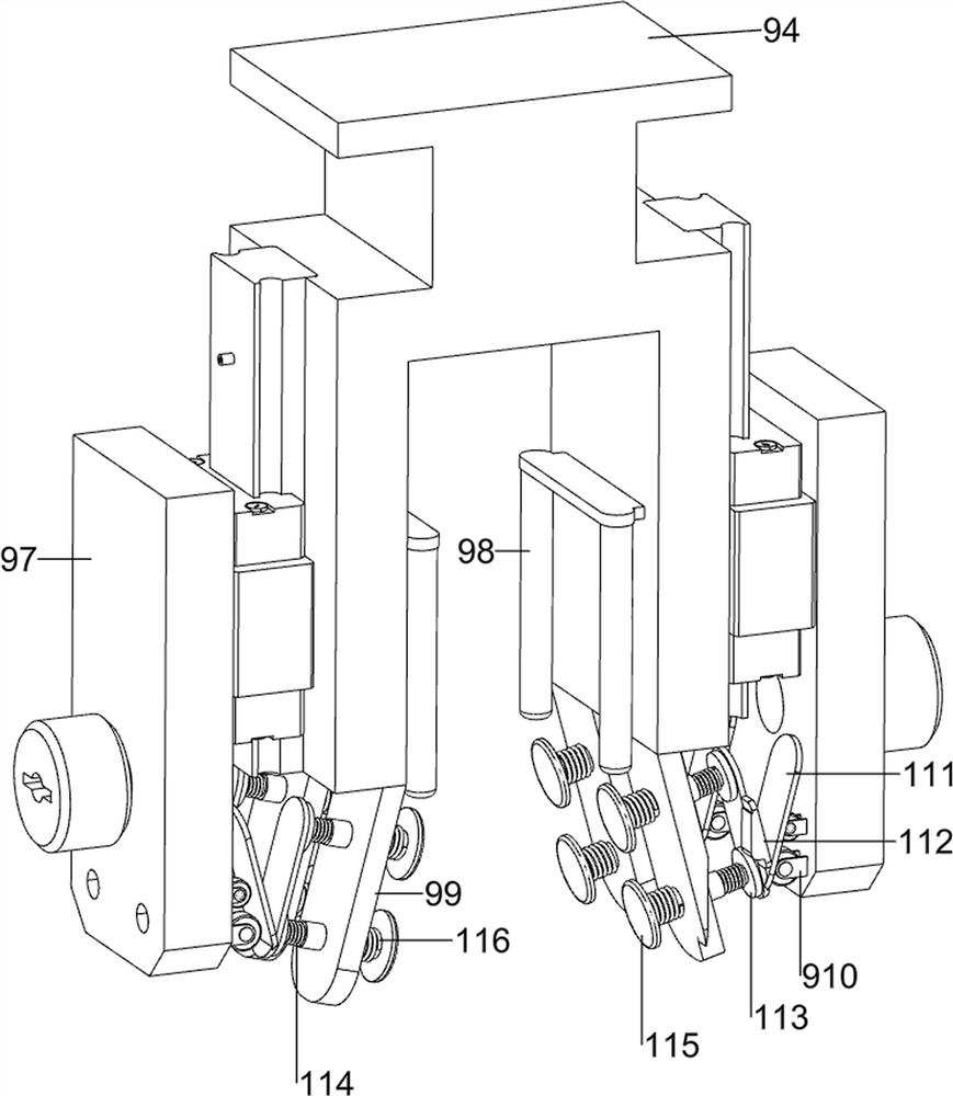
[0042] On the basis of Example 1, as Figure 4 and Figure 9 As shown, it also includes a mask fixing mechanism 11, and the mask fixing mechanism 11 includes a third fixing block 111, a first magnet 112, a first pressing frame 113, a first tension spring 114, a second pressing frame 115 and a second tension spring 116. The left and right sides of the first fixing block 99 are slidably provided with a second pressing frame 115. The second pressing frame 115 slides inward to fix both sides of the lower part of the mask. The inner side of the second pressing frame 115 is surrounded by a second tension spring 116. , the two ends of the second tension spring 116 are respectively connected with the second pressing frame 115 and the first fixing block 99, the outer side of the second pressing frame 115 is slidably provided with the first pressing frame 113, the first pressing frame 113 and the second pressing frame The first tension springs 114 are connected between the 115 . The fi...


PUM


Abstract

The invention relates to performance detection equipment, in particular to mask nose bridge strip performance detection equipment. The invention provides performance detection equipment for a mask nose bridge strip to be written. Mask nose bridge strip performance detection equipment comprises a supporting frame, supporting rods, first rollers, a first conveying belt, a mask mold and the like, the supporting rods are symmetrically arranged on the left side and the right side of the top of the supporting frame front and back, the first rollers are rotationally connected between the upper portions of the two supporting rods on the same side in the longitudinal direction, and the first conveying belt is connected between the first rollers in a wound mode. And mask molds are uniformly arranged on the first conveying belt at intervals. The nose bridge strip is bent downwards through the nose bridge strip pressing frame, then unqualified masks and qualified masks are conveyed through the second conveying belt and the first conveying belt respectively, detection of the bending resistance of the nose bridge strips of the masks is achieved, operation is easy and convenient, and practicability is high.

Description

technical field [0001] The invention relates to a performance testing device, in particular to a performance testing device for the nose bridge strip of a mask. Background technique [0002] Masks are daily anti-infection protective equipment. In order to make masks fit more firmly with people's faces and achieve basic protection, manufacturers will weld nose bridge strips at the nose bridge when producing masks, and some unqualified nose bridge strips are bent. Afterwards, it will be restored like a memory metal, and the bending resistance is poor, resulting in a poor fit between the mask and the face, resulting in poor protection. In order to improve the protection of the mask, it is necessary to detect and pick out this batch of unqualified masks for rework . [0003] The patent application CN202614954U, the date of publication is 2012121, discloses a mask nose bridge detector, including an infrared sensor and an alarm, and an adjustment rod is symmetrically arranged on ...

Claims


Application Information

Patent Timeline
Patent Type & Authority Applications(China)
IPC IPC(8): G01N3/20G01N3/08G01N3/04
CPCG01N3/20G01N3/08G01N3/04G01N2203/0023G01N2203/0682
Inventor 刘桂兰
Owner 刘桂兰
Why Eureka
Try Eureka