
Eureka
For R&D, Eureka makes reading and utilizing patents & technical documents easy.
Eureka AIR
Designed for self-driven R&D workflows. Generate viable solutions, solve complex R&D challenges, empower your innovation with AI.

Eureka Materials
Designed for material experts only. Revolutionize your material R&D, from search, analyze, to developing new materials.

TechResearch
Generate reliable direction feasibility study reports for your R&D in just a few steps.

TechSeek
Discover and master advanced knowledge NOW. Basics, ideas, possibilities, all at once.

TechMind
As an expert in R&D Theories, TechMind can generates customized viable solutions instantly.

TechRisk
Analyze your overall solution with one click, know your potential R&D risks in advance.

TechMonitor
Get weekly tech updates, stay abreast of the latest tech innovations and key insights.
Programmable reflector
A technology of reflectors and reflector arrays, which is applied in the directions of radio wave reflection/re-radiation, instruments, and utilization of re-radiation, etc., and can solve problems such as radar system identification and failure to reach protection targets
- Summary
- Abstract
- Description
- Claims
- Application Information
AI Technical Summary
Problems solved by technology
Method used
Image

Examples
Embodiment 1
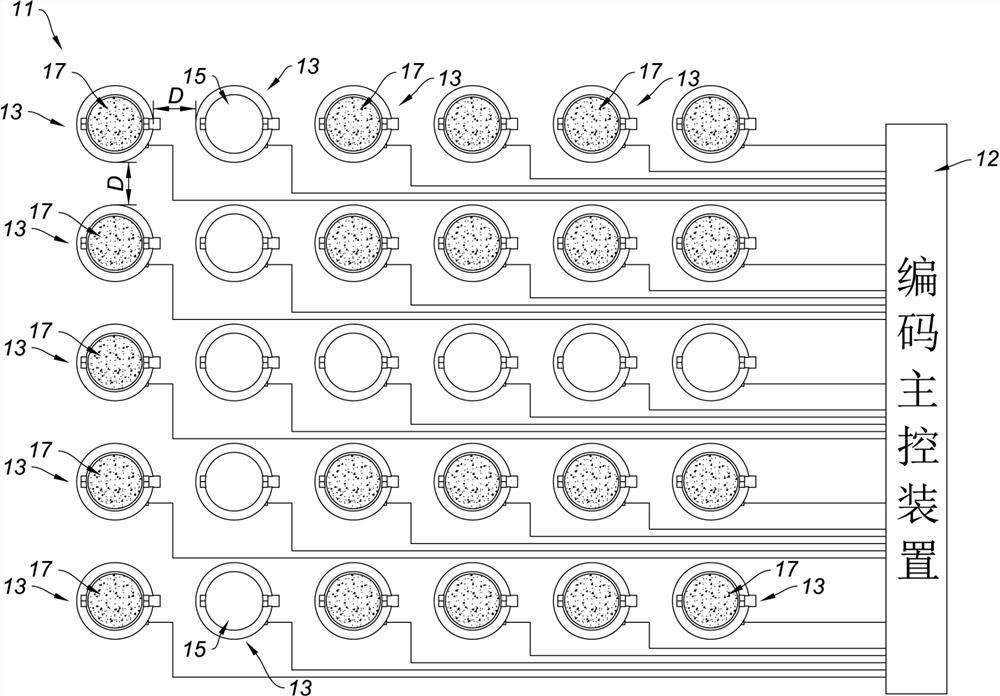
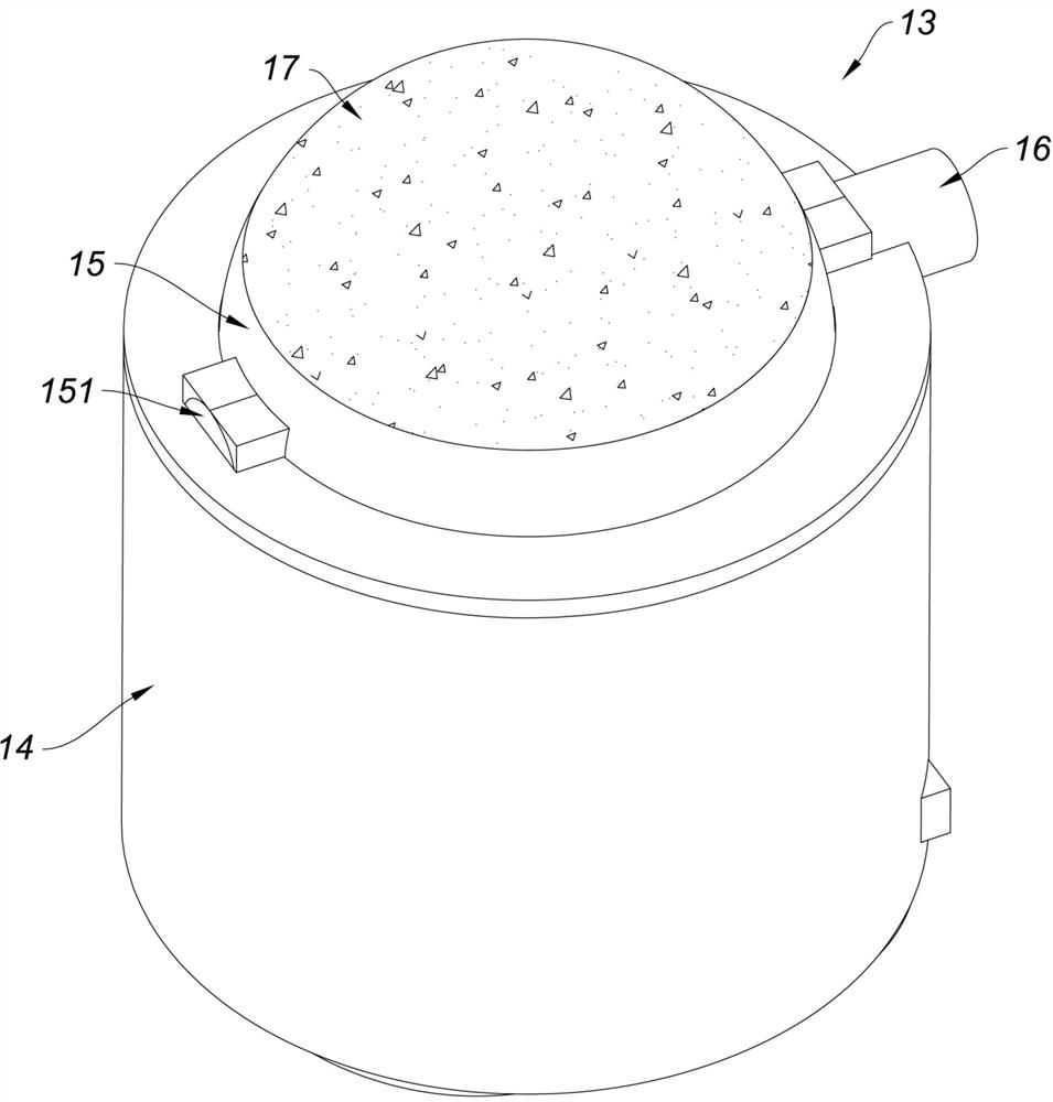
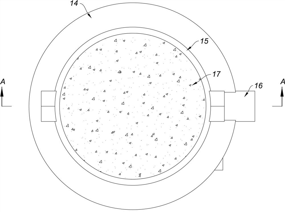
[0032] like figure 1 , figure 2 , image 3 , Figure 4As shown, a programmable reflector in this embodiment includes a reflector array 11 and a coding master control device 12; the reflector array 11 includes 30 reflection units 13, and the 30 reflection units 13 are formed by a planar rectangular array In the reflector array 11, the distance D between two adjacent reflecting units 13 is 30 cm. Each reflecting unit 13 includes a base 14 , an electromagnetic wave lens 15 , a rotating mechanism 16 and a reflecting member 17 . The rotating mechanism 16 is mounted on the base 14 . The electromagnetic wave lens 15 is a spherical structure. The rotation axis of the electromagnetic wave lens 15 relative to the base 14 is L1 . The electromagnetic wave lens 15 is driven by the rotating mechanism 16 to move relative to the base 14 . The structure that the electromagnetic wave lens 15 is installed on the base 14 is specifically: a rotating part 151 is fixed on both sides of the ele...
Embodiment 2
[0036] The difference between this embodiment and Embodiment 1 is that: the reflection combination figure is formed by the combination of the reflection units 26 of 4 kinds of target postures; Figure 5 As shown, there are five rows of reflection units 26 in this embodiment, from top to bottom are the first row 21 , the second row 22 , the third row 23 , the fourth row 24 and the fifth row 25 , wherein the first row 21 , the third row 25 The reflection unit 26 in the five elements 25 is in the first target attitude, and the central reflection direction of the main reflection surface of the reflector 27 of the reflection unit 26 in the first target attitude is the inward direction perpendicular to the paper surface; the second The reflection unit 26 in row 22 is in the second target attitude, the reflection unit 26 in the fourth row 24 is in the third target attitude, and the reflector of the reflection unit 26 in the second row 22 The central reflection direction of the main r...
Embodiment 3
[0038] The difference between this embodiment and Embodiment 1 is that: Image 6 As shown, the outline shape of the reflector array 32 in this embodiment is a triangle, and the reflecting units 31 in the first reflecting state of the reflector array 32 under the action of the encoding master device 33 together form a "herringbone"-shaped pattern . like Image 6 As shown, in the reflection unit 31 in the first reflection state, no reflection member can be seen, and the central reflection direction of the main reflection surface of the reflection member of these reflection units 31 is perpendicular to the outward direction of the paper surface. Such a design can reflect different radar wave reflection characteristics from Embodiment 1 when in use, so as to meet the needs of different application scenarios.
PUM
 Abstract
Description
Claims
Application Information
 - R&D Engineer
- R&D Manager
- IP Professional
- Industry Leading Data Capabilities
- Powerful AI technology
- Patent DNA Extraction
Browse by: Latest US Patents, China's latest patents, Technical Efficacy Thesaurus, Application Domain, Technology Topic, Popular Technical Reports.
© 2024 PatSnap. All rights reserved.Legal|Privacy policy|Modern Slavery Act Transparency Statement|Sitemap|About US| Contact US: help@patsnap.com