
Cutting layout design method suitable for introducing customized chip and chip prepared by cutting layout design method

A layout design and chip technology, applied in manufacturing computing systems, computer-aided design, CAD customization/personalization, etc., can solve the problems of cutting yield and low efficiency, to ensure reliability, reduce cutting times, and reduce secondary The effect of cutting risk

Active Publication Date: 2022-05-27
成都复锦功率半导体技术发展有限公司
View PDF7 Cites 8 Cited by
  • Summary
  • Abstract
  • Description
  • Claims
  • Application Information

AI Technical Summary

Problems solved by technology

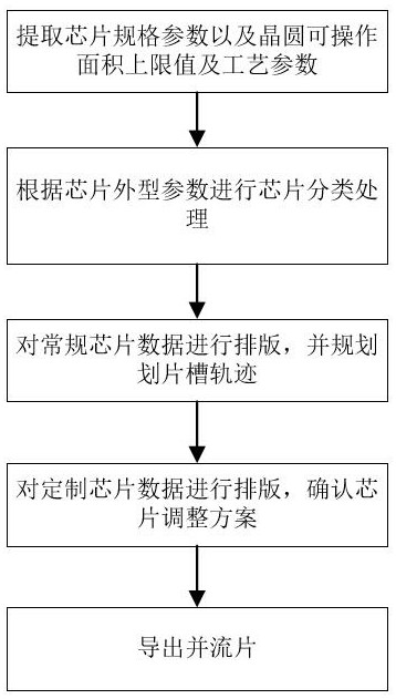
[0005] The purpose of the present invention is to solve the problem of low cutting yield and efficiency caused by the introduction of customized chips in the layout design process, and provide a cutting layout design method suitable for introducing customized chips and chips prepared therefrom

Method used


Image

  • Cutting layout design method suitable for introducing customized chip and chip prepared by cutting layout design method
  • Cutting layout design method suitable for introducing customized chip and chip prepared by cutting layout design method
  • Cutting layout design method suitable for introducing customized chip and chip prepared by cutting layout design method

Examples


Embodiment Construction

[0062] The technical solutions of the present invention will be clearly and completely described below with reference to the accompanying drawings. Obviously, the described embodiments are part of the embodiments of the present invention, but not all of the embodiments. Based on the embodiments of the present invention, all other embodiments obtained by those of ordinary skill in the art without creative efforts shall fall within the protection scope of the present invention.

[0063] In the description of the present invention, it should be noted that "center", "upper", "lower", "left", "right", "vertical", "horizontal", "inner", "outer", etc. The indicated direction or positional relationship is based on the direction or positional relationship described in the drawings, and is only for the convenience of describing the present invention and simplifying the description, rather than indicating or implying that the indicated device or element must have a specific orientation or...


PUM


Abstract

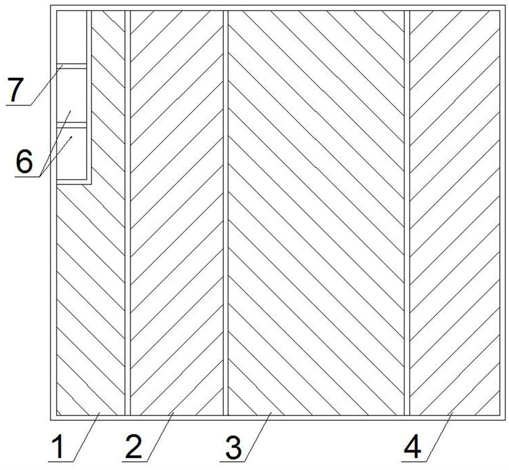
The invention discloses a cutting layout design method suitable for introducing a customized chip and a chip prepared through the cutting layout design method, and belongs to the technical field of semiconductors. Chip classification processing is carried out according to chip appearance parameters, and conventional chip data and customized chip data are obtained; performing typesetting calculation according to the conventional chip data and the upper limit value of the operable area of the wafer, and outputting all layout design sketches with penetrating scribing grooves; and performing secondary design on the reserved position in the layout design sketch according to the customized chip data, and outputting a secondary layout design sketch. According to the method, a conventional chip is firstly subjected to typesetting design to obtain a layout design sketch penetrating through a scribing groove, so that the secondary cutting risk is greatly reduced; under the condition that the area is reserved, the scribing groove design of the customized chip is planned, the overall change of the layout design sketch is controlled within the minimum range, and the layout design sketch compatible with the customized chip is obtained on the basis that conventional chip layout is not affected, so that the layout cutting yield and efficiency are guaranteed.

Description

technical field [0001] The invention relates to the technical field of semiconductors, in particular to a cutting layout design method suitable for introducing custom chips and a chip prepared therefrom. Background technique [0002] The layout design of integrated circuits plays a crucial role in the design process of silicon-based semiconductors, and is an important intermediate link in the circuit design and the driving process. As the development of silicon-based power semiconductors in China is becoming more and more mature, the requirements for high-yield and high-efficiency layout drawing have gradually emerged, and the layout design of silicon-based power semiconductors with stable and reliable, strong process affinity, easy cutting and picking, and high area utilization will be quickly obtained. Help further save chip costs, effectively shorten the chip development cycle, and help products occupy the civilian market faster. [0003] The chip form that can directly ...

Claims


Application Information

Patent Timeline
Patent Type & Authority Applications(China)
IPC IPC(8): G06F30/392H01L27/02G06F113/18G06F111/16
CPCG06F30/392H01L27/0207G06F2113/18G06F2111/16Y02P90/30
Inventor 不公告发明人
Owner 成都复锦功率半导体技术发展有限公司
Learn More