Biomass gas internal combustion generator set

A technology for internal combustion generator sets and biomass gas, which is applied in the direction of internal combustion piston engines, combustion engines, combustion air/combustion-air treatment, etc., and can solve problems such as failure to start, low calorific value of biomass gas, and difficulty in mixing air completely. Achieve the effect of improving uniformity and improving uniformity

Active Publication Date: 2022-05-31
山东赛马力发电设备有限公司
View PDF4 Cites 0 Cited by
  • Summary
  • Abstract
  • Description
  • Claims
  • Application Information

AI Technical Summary

Problems solved by technology

[0004] However, biomass gas has low calorific value and complex composition. It is difficult or even impossible to start the engine when using a general gas mixer. In the prior art, the ratio of air to gas is automatically adjusted to make the generator set easy to start. However, the adjusted The air is difficult to mix completely under the condition of rapid intake

Method used


Image

  • Biomass gas internal combustion generator set
  • Biomass gas internal combustion generator set
  • Biomass gas internal combustion generator set

Examples


no. 1 example

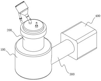
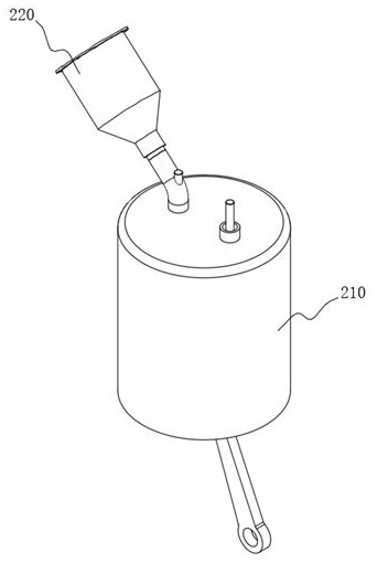
[0040] The first embodiment, this embodiment mainly discloses the working principle of the crank linkage mechanism, please refer to figure 2 As shown, the internal combustion mechanism 200 includes an outer housing 210, see Figure 7As shown, a combustion chamber is arranged inside the outer casing 210, and a piston 211 is slidably connected to the combustion chamber. A connection groove 2111 is opened at the bottom of the piston 211, and a connecting rod 212 is connected to the connection groove 2111 in rotation, and is driven by the pressure generated by the combustion of fuel in the combustion chamber. The piston 211 moves down, and then the lower part of the connecting rod 212 rotates and is connected with a crank. The connecting rod 212 that moves down drives the crank and the flywheel to rotate, and the connecting rod 212, the crank and the flywheel form a crank linkage mechanism, and then the piston 211 is driven Under the action of the inertia of the connecting rod 21...

no. 2 example

[0048] For a second example, see Figure 5-Figure 7 As shown, the outer casing 210 is provided with a hot air delivery group 230, the hot air delivery group 230 includes a heat collection ring 231, and the heat collection cavity 231A is formed by closing the heat collection ring 231 and the outer casing 210, and the hot air delivery group 230 also includes The conduction ring 232, the conduction ring 232 is arranged outside the outer tube body 221, and the conduction cavity 232A is formed by closing between the conduction ring 232 and the outer tube body 221, and the transmission pipe 233 is arranged between the heat collection ring 231 and the conduction ring 232, and the transmission pipe 233 A negative pressure pump 234 is provided so that the heat generated during combustion in the combustion chamber is conducted to the heat collecting chamber 231A by the outer wall of the outer shell 210, and then the heat is transferred to the conduction chamber 232A through the transfer ...


PUM


Abstract

The invention relates to an internal combustion generating set, in particular to a biomass gas internal combustion generating set. The device comprises a driving main body, an internal combustion mechanism is arranged at the top of the driving main body, a crank-link mechanism is arranged in the driving main body, the internal combustion mechanism uses biomass gas as energy to drive the crank-link mechanism for transmission, a power generation main body is arranged on one side of the driving main body, and a storage battery is arranged on one side of the power generation main body. According to the invention, the mixing inner pipe and the mixing outer pipe are arranged, and the outer pipe mixing groove and the inner pipe mixing groove are correspondingly formed outside the mixing inner pipe and the mixing outer pipe, so that biomass gas and air can converge and circulate in the outer pipe mixing groove and the inner pipe mixing groove after entering the outer pipe body, and shuttle back and forth between the outer mixing cavity and the inner mixing cavity in the circulation process; therefore, the purpose of mixing the biomass gas and the air is achieved.

Description

technical field [0001] The invention relates to an internal combustion generator set, in particular to a biomass gas internal combustion generator set. Background technique [0002] The internal combustion generator set usually includes a driving device, a power generating device, and a power storage device. The power generating device is driven by the driving device, so that the internal rotor cuts the magnetic induction line to generate current, and the generated current charges the power storage device, usually driving The devices all use the internal combustion mechanism to increase power, and there are many kinds of fuel for the internal combustion mechanism. At present, in order to protect the environment, the focus is on researching biomass gas. [0003] Biomass gas is an indirect liquefaction technology. Biomass is gasified by thermochemical method to produce crude gas, and then high-quality synthesis gas is obtained through gas purification and component modulation....

Claims


Application Information

Patent Timeline
Patent Type & Authority Applications(China)
IPC IPC(8): F02B63/04F02M21/02F02M21/04F02M31/06
CPCF02B63/042F02M21/0215F02M21/04F02M21/042F02M31/06F02M31/045Y02T10/30
Inventor 张连波张利平王建辉吕小刚黄帅虎姚树栋殷爱军
Owner 山东赛马力发电设备有限公司
Why Eureka
Try Eureka