Eureka AIR delivers breakthrough ideas for toughest innovation challenges, trusted by R&D personnel around the world.

Threading device of firework machine

A threading device and fireworks technology, applied in pyrotechnics, offensive equipment, weapon types, etc., can solve the problems of high production cost, increased production time, low production efficiency, etc., and achieve the effect of saving generation time and improving production efficiency

Pending Publication Date: 2022-05-31
泉州湖南大学工业设计与机器智能创新研究院
View PDF0 Cites 0 Cited by
  • Summary
  • Abstract
  • Description
  • Claims
  • Application Information

AI Technical Summary

Problems solved by technology

At present, this process is done manually in actual production, which has low work efficiency, high labor intensity, large number of workers and high production cost.
[0003] Existing equipment is for single fireworks tubes to be cut one by one. The fireworks tubes are pushed horizontally along the direction perpendicular to the central axis of the fireworks tubes to the subsequent processing station. After punching and inserting, they are combined into rows. In the process, because the actual requirements are different, the specifications of the lead wires are also different. However, the existing technology usually only uses one specification of the lead wire. If a different specification of the lead wire is required, the lead wire needs to be replaced, which greatly increases the production time. , so that the production efficiency is low, and it is not easy to align the holes punched first when inserting and introducing, which is easy to cause errors and affect the quality

Method used


Image

  • Threading device of firework machine
  • Threading device of firework machine
  • Threading device of firework machine

Examples


Embodiment Construction

[0044] The present invention will be further described below through specific embodiments.

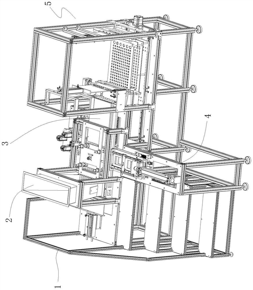
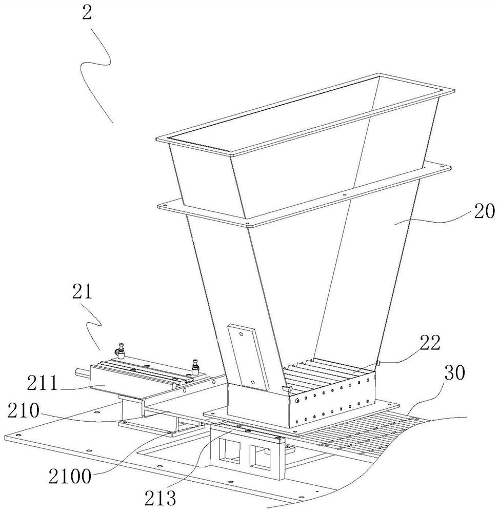
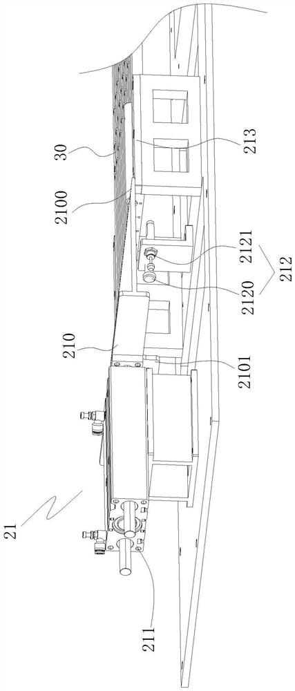
[0045] refer to Figure 1 to Figure 15 , a firework machine for automatically arranging and assembling fireworks tubes of the present invention, comprising a frame 1, a feeding device 2, a conveying device 3, a threading device 4 and an orientation arrangement 5, a feeding device 2, a conveying device 3, and a threading device 4 And alignment arrangement device 5 is arranged on frame 1. The feeding device 2 is used to transport the fireworks tubes to the conveying device 3, and the conveying device 3 includes a conveying plate 30 and a pressing plate 31, and the conveying plate 30 is used to accept the fireworks tubes transported by the feeding device 2 and make the fireworks The cylinders are arranged in parallel at intervals and conveyed along the conveying direction. The conveying plate 30 is divided into a material receiving end, a punching position, a threading position and a dis...


PUM


Abstract

The invention provides a threading device of a firework machine, which is arranged on a rack of the firework machine, is used for threading and punching a threading position and a punching position of a conveying device of the firework machine, and comprises a moving mechanism, a wire supply mechanism, a steel needle and a wire leading pipe, the material pressing plate is arranged above the firework machine in a lifting mode and can press firework cylinders on the conveying plate, the steel needles and the wire guiding pipes are movably arranged on a machine frame of the firework machine and located on one side of the conveying plate, the steel needles and the wire guiding pipes are arranged in parallel at intervals, and the interval between the steel needles and the wire guiding pipes is equal to the length of one firework cylinder. The moving mechanism is connected with and drives the steel needles and the thread guide pipes to move in the direction perpendicular to the conveying direction of the firework barrels, the thread supply device is arranged on the firework machine rack and located on the side, away from the moving mechanism, of the conveying plate, and the thread outlet end of the thread supply device faces the threading position of the conveying plate and right faces the thread guide pipes.

Description

technical field [0001] The invention relates to the field of fireworks machines, in particular to a threading device for fireworks machines. Background technique [0002] In the process of making fireworks, there is a process commonly known as "pot grouping". First, multiple fireworks tubes are glued together to form a row, and holes are drilled into two adjacent tubes to insert the overfire lead, and then the multiple rows of fireworks tubes are glued together. Combined into a block whole. At present, this process is all done manually in actual production, which has low work efficiency, high labor intensity, large number of workers, and high production cost. [0003] Existing equipment is for single fireworks tubes to be cut one by one. The fireworks tubes are pushed horizontally along the direction perpendicular to the central axis of the fireworks tubes to the subsequent processing station. After punching and inserting, they are combined into rows. In the process, becau...

Claims


Application Information

Patent Timeline
Patent Type & Authority Applications(China)
IPC IPC(8): F42B4/30
CPCF42B4/30
Inventor 刘永红涂振民黄金祥
Owner 泉州湖南大学工业设计与机器智能创新研究院
Why Eureka
Eureka Blog
Learn More