
Oil-cooled motor rotor

A motor rotor and rotor technology, applied in the direction of motors, electric components, electric vehicles, etc., can solve the problems of overheating and demagnetization of magnetic steel, affecting the performance, reliability and life of the motor, and the inability to cool the iron core and windings, etc., to achieve a balanced temperature distribution , Improve continuous working power and improve system reliability

Pending Publication Date: 2022-05-31
苏州睿控电动有限公司
View PDF6 Cites 0 Cited by
  • Summary
  • Abstract
  • Description
  • Claims
  • Application Information

AI Technical Summary

Problems solved by technology

The highest temperature of the traditional water-cooled motor is located at the end of the winding. The traditional oil-cooled motor uses the stator spray method to cool the stator end winding, so that the highest temperature of the motor is located at the center of the stator core and the rotor core. The local high temperature severely limits the The oil-cooled motor has a high load and continuous power. In severe cases, the magnet will be overheated and demagnetized, which will affect the performance, reliability and life of the motor.
[0003] At present, most of the existing oil-cooled motors spray the windings at the end of the motor stator, and cannot cool the iron core and windings inside the motor rotor and the center of the stator iron core.

Method used


Image

  • Oil-cooled motor rotor
  • Oil-cooled motor rotor
  • Oil-cooled motor rotor

Examples


Embodiment Construction

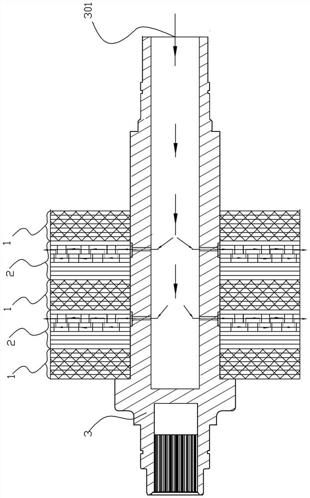
[0041] An oil-cooled motor rotor, for specific embodiments see Figure 1-Figure 8 , which consists of a rotor core assembly 1, a rotor integrated oil circuit core assembly 2, and an oil-cooled motor shaft 3;

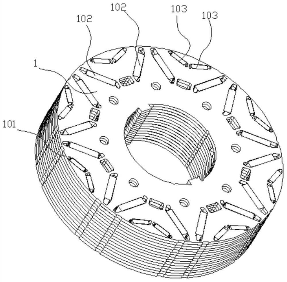
[0042] The rotor core assembly 1 is made of laminated rotor punches 101, and is equipped with magnetic steel 102 and magnetic steel 103. There are protruding keys in the inner hole of the rotor iron core assembly, and the key through the inner hole of the rotor iron core can be cooled with oil. The keyway 304 on the motor shaft 3 fits closely;

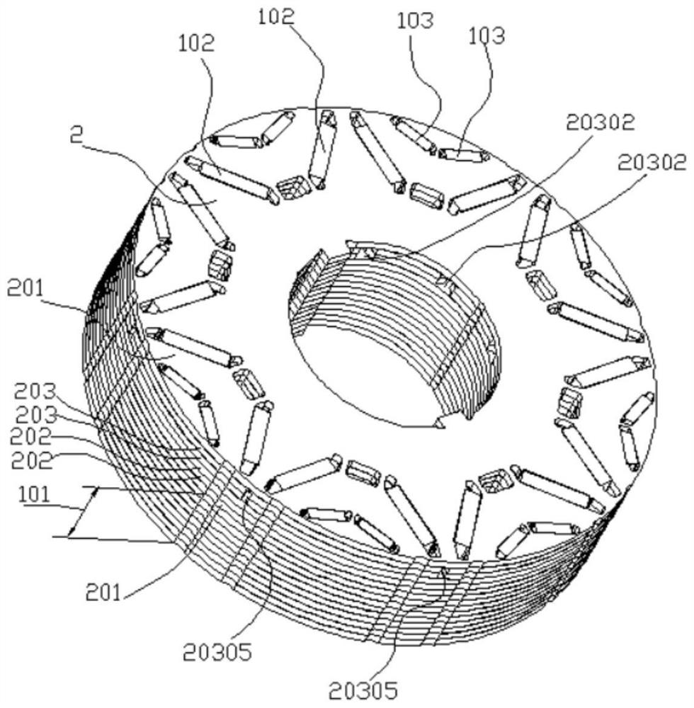
[0043] The rotor integrated oil circuit core assembly 2 forms an oil channel in the rotor integrated oil circuit core through the combination of rotor punches of different structures. In specific implementation, the rotor integrated oil circuit iron core assembly 2 is formed by stacking the rotor punching plate 101, the rotor oil isolation punching plate 201, the rotor oil guiding punching plate 202, and the rotor oil injection ...


PUM


Abstract

The invention provides an oil-cooled motor rotor which can well solve the problems of cooling of a rotor central iron core and magnetic steel and cooling of a stator iron core central winding. The motor comprises a rotor iron core assembly, a rotor integrated oil path iron core assembly and an oil cooling motor shaft. A plurality of rotor iron core assemblies and rotor integrated oil way iron core assemblies are sequentially and fixedly arranged in the axial area of the oil-cooled motor shaft in a spacer bush mode, one rotor integrated oil way iron core assembly is arranged between every two adjacent rotor iron core assemblies, and another rotor iron core assembly is arranged between every two adjacent rotor integrated oil way iron core assemblies; rotor iron core assemblies are arranged at the two axial ends of the oil-cooled motor shaft respectively. Each group of rotor iron core assembly is formed by laminating a plurality of rotor punching sheets and is provided with magnetic steel; each rotor integrated oil way iron core assembly comprises an oil way lamination assembly, oil inlets are annularly distributed in the inner diameter of each oil way lamination assembly, a plurality of oil spraying openings are annularly distributed in the outer diameter of each oil way lamination assembly, and the oil inlets correspond to the oil spraying openings respectively.

Description

technical field [0001] The invention relates to the technical field of motor rotor structure, in particular to an oil-cooled motor rotor. Background technique [0002] As the power density requirements of permanent magnet synchronous motors for new energy vehicles increase, the traditional water-cooling method cannot meet the cooling requirements due to the long heat conduction path. The oil-cooled motor uses a heat transfer method in which the cooling oil directly contacts the heating parts of the motor. The heat transfer effect is improved, and the power density of the motor is greatly increased. The heat source of the permanent magnet motor is mainly concentrated in the motor stator core, stator winding, motor rotor core, magnetic steel and other components, and generally the stator core and stator winding generate the most heat. The highest temperature of the traditional water-cooled motor is located at the end of the winding. The traditional oil-cooled motor uses the s...

Claims


Application Information

Patent Timeline
IPC IPC(8): H02K1/32H02K9/19H02K9/193H02K1/276
CPCH02K1/32H02K9/19H02K9/193H02K1/276H02K2213/03Y02T10/64
Inventor 王有林施绍有
Owner 苏州睿控电动有限公司
Learn More