Vehicle power battery safety monitoring device
A battery safety and monitoring device technology, applied in battery/fuel cell control devices, vehicle components, vehicle energy storage, etc., can solve problems such as power battery damage, and achieve the effect of improving the evacuation of heat energy
- Summary
- Abstract
- Description
- Claims
- Application Information
AI Technical Summary
Problems solved by technology
Method used
Image
Examples
Embodiment 1
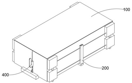
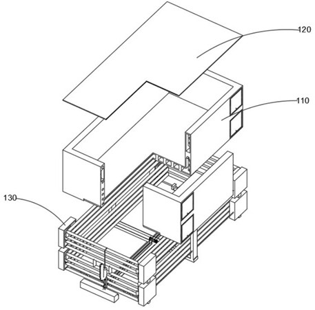
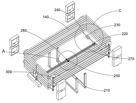
combine Figure 1-9 As shown, a vehicle power battery safety monitoring device provided by the present invention includes a protection mechanism 100, a bottom transmission mechanism 200, a drum liquid cooling mechanism 300 and a hot pressing mechanism 400, wherein the bottom transmission mechanism 200 is installed on the protection mechanism 100. , the drum liquid cooling mechanism 300 is connected to the protection mechanism 100 , in addition, the hot pressing mechanism 400 is installed between the protection mechanism 100 and the bottom transmission mechanism 200 .
[0021] The protective mechanism 100 includes an accommodation box 110, a heat transfer top plate 120, a hood 130 and a cold flow pipe 140. The bottom-mounted transmission mechanism 200 includes an air groove 210, a main pad 220, an auxiliary pad 230, a horizontal shaft 240, a vertical plate 250, The air blowing part 260 and the chain 270, the drum liquid cooling mechanism 300 includes the water tank 310, the firs...
Embodiment 2
combine figure 2 , 4 As shown in , 5 and 6, on the basis of the first embodiment, the bottom plate of the container box 110 is provided with ventilation grooves, the interior of the container box 110 is provided with vertically distributed matrix air holes, and the edge position of the container box 110 is provided with Horizontal holes distributed along the vertical direction, wherein a rectangular cavity is opened inside the heat transfer top plate 120, and one end of the heat transfer top plate 120 is provided with an air hole communicating with the rectangular cavity, and the arc pipe 441 is away from the vertical pipe at one end of the exhaust pipe 443. Connected to the rectangular cavity, in addition, the inner wall of the hood 130 is provided with an inwardly recessed hole, and the outer end of the shaft in the middle of the first turbine part 320 or the second turbine part 330 is movably installed with a cylindrical protrusion, and the cylindrical protrusion is The pr...
Embodiment 3
[0027] By installing the air groove 210 at the bottom of the accommodating box 110, and the air groove 210 and the main cushion member 220 are distributed on the accommodating box 110 in a cross-shaped state, and the directional guidance of the fan blades in the two inflating members 260 to agitate the airflow, In this way, the return pipe 340 running through the protruding columns at both ends of the air groove 210 can be rapidly cooled locally, and the gear connected to the inner end of the air blowing member 260 is engaged with the chain 270, and the air blowing member 260 is located on the inner side of the vertical plate 250. middle.
PUM
 Abstract
Description
Claims
Application Information
 - R&D
- Intellectual Property
- Life Sciences
- Materials
- Tech Scout
- Unparalleled Data Quality
- Higher Quality Content
- 60% Fewer Hallucinations
Browse by: Latest US Patents, China's latest patents, Technical Efficacy Thesaurus, Application Domain, Technology Topic, Popular Technical Reports.
© 2025 PatSnap. All rights reserved.Legal|Privacy policy|Modern Slavery Act Transparency Statement|Sitemap|About US| Contact US: help@patsnap.com


